Grinding machine

a technology of grinding machine and workpiece carrier, which is applied in the direction of grinding machine components, grinding machines, other manufacturing equipment/tools, etc., can solve the problems of unfavorable workpiece machining accuracy, long adjustment time for positioning workpiece carriers, and inconvenient etc., to achieve precise, easy and quick adjustment of tool carriers, and fast and accurate adjustment of workpiece carriers

Inactive Publication Date: 2005-09-08
ALFRED H SCHUTTE
View PDF10 Cites 13 Cited by
  • Summary
  • Abstract
  • Description
  • Claims
  • Application Information

AI Technical Summary

Benefits of technology

[0005] It is the primary object of the invention to provide a grinding machine of the above-mentioned type with which a fast and very accurate adjustment of the workpiece carrier for the support of the workpiece at the grinding location is possible. Accordingly, the method according to the invention shall provide for a particularly precise, easy and quick adjustment of the tool carrier. According to the invention, this object is achieved by the grinding machine in that the workpiece carrier is developed as a workpiece guide system (WGS), which comprises a workpiece reception and an adjustment device with which the workpiece reception can be adjusted in its height displacement and lateral displacement from the axis of the workpiece spindle or the workpiece which is clamped therein.
[0006] With the help of the adjustment device, the workpiece reception of the workpiece guide system can be exactly adjusted in two axes transversely to the longitudinal axis of the workpiece spindle, so that it is achieved with little effort in a short time that the workpiece to be machined is supported in the workpiece reception exactly at the desired height and lateral position at the grinding location. That is, it is not necessary anymore to adjust the entire workpiece carrier relative to the machine bed in the height and lateral position as in the state of the art, but only the workpiece reception is adjusted upwards or downwards or transverse, i.e. sideways to the longitudinal axis of the workpiece with the help of the adjustment device. The secondary process times or setting periods of the machine can thereby be shortened considerably during the adjustment.
[0008] It is of particular advantage if the workpiece guide system is arranged in a moveable manner at the machine bed relative to the workpiece spindle or the workpiece clamped therein. Thereby, the workpiece guide system essentially keeps its position relative to the grinding spindle. It is then possible to machine an elongated workpiece in the grinding machine, whereby either the workpiece spindle with the workpiece clamped therein, and possibly a support receiving the free end of the workpiece moves along the machine bed, while the grinding spindle and the workpiece guide system keep their position relative to the machine bed, or the workpiece spindle and possibly the support are driven along the machine bed together with the workpiece guide system and the workpiece is thereby machined along its length.
[0012] It is advantageous if the workpiece reception comprises at least an exchangeable prism element. By the exchange of the prism element, the workpiece reception can be optimally adapted to different workpiece diameters.
[0015] It is advantageous if the support block is provided with two support axes being arranged under an angle to form an approximately v-shaped groove and that the two support areas are simultaneously grinded with the same grinding tool, so that after the correct adjustment the workpiece will be guided between two contact lines being parallel with each other.

Problems solved by technology

It has been found that the adjustment of such a workpiece carrier generally needs a lot of time and experience.
In particular, in cases in which the workpieces are to be ground, the diameter of which are very small compared to their length, for example during the production of boring or milling workpieces with a diameter of only 1 mm or even smaller, the exact positioning of the workpiece carrier necessary for the accurate machining of the workpiece can require a long adjustment time in the region of the grinding location, during which one cannot work with the machine.
While such long setting periods can be acceptable with workpieces to be produced in large quantities, they are particularly undesired if only a few workpieces are to be produced with the machine adapted once, before it is converted again.

Method used


Image

  • Grinding machine
  • Grinding machine
  • Grinding machine

Examples


Embodiment Construction

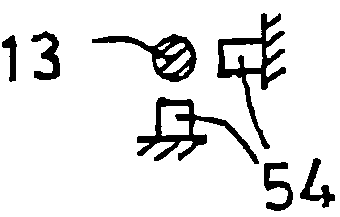
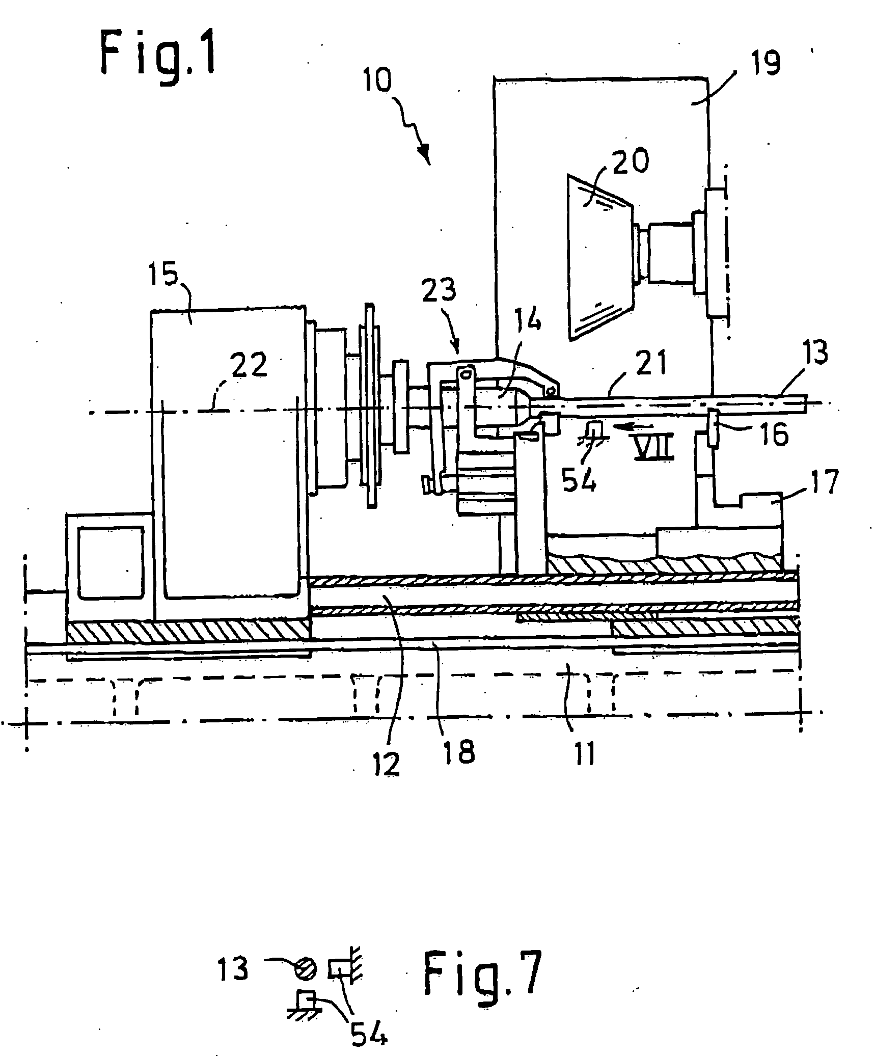
[0026] The grinding machine 10 shown schematically from the side in FIG. 1 comprises a machine bed 11 with a guide 12, which, in the longitudinal direction, runs parallel to a workpiece 13 to be machined.

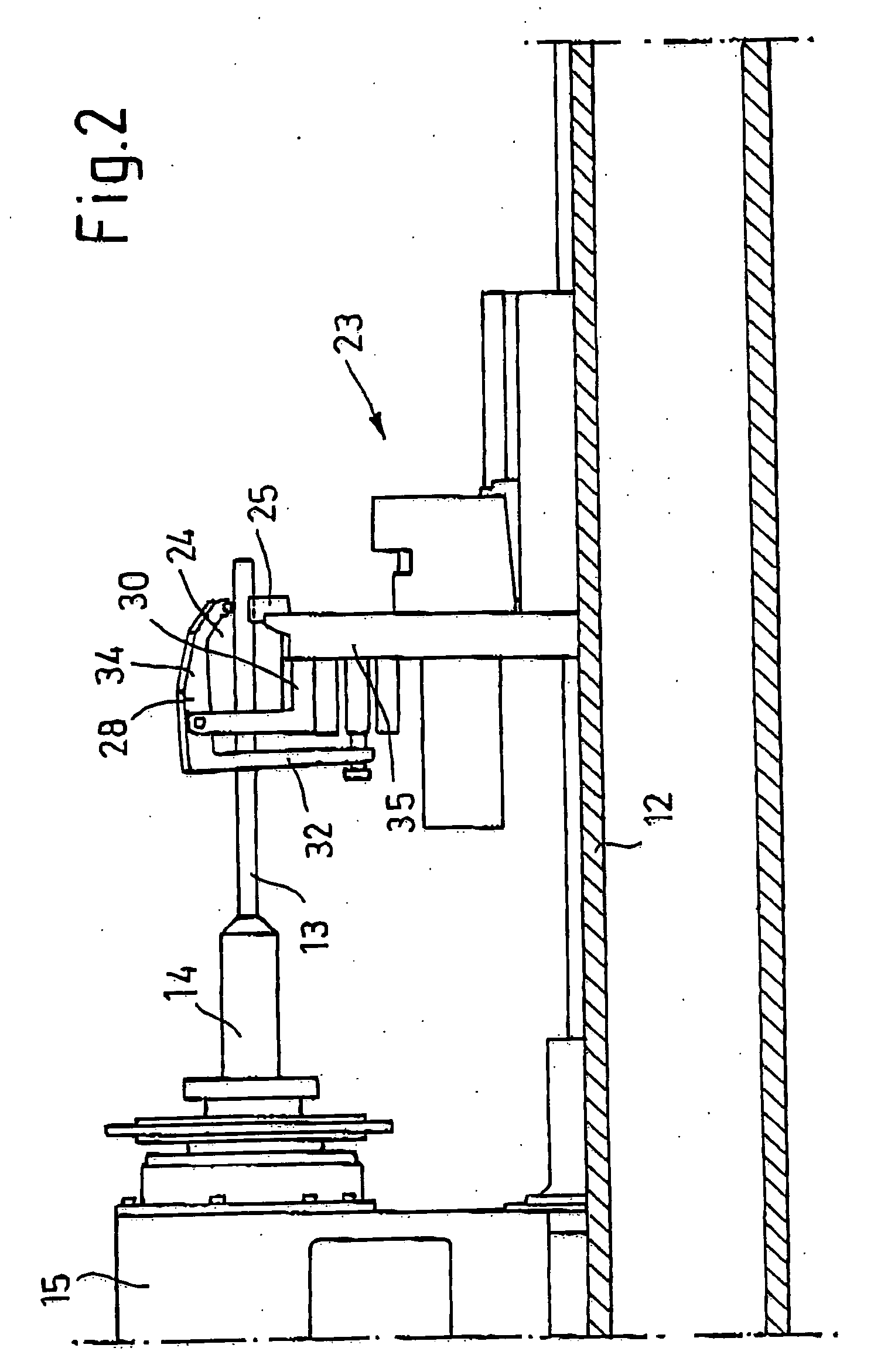
[0027] The workpiece 13 is clamped with its tail end into a workpiece spindle 14 which can be displaced longitudinally together with its headstock 15 along the guide 12 of the machine bed 11. The other end of the workpiece 13 (to the right in FIG. 1) is supported by a support prism 16 of a support 17, which is also mounted in a longitudinally displaceable manner on the guide 12 and which can be displaced together with the headstock 15. To this end, the headstock 15 and the support 17 are connected to one another by means of a coupling rod 18 with a variable distance.

[0028] For the machining of the workpiece 13, the grinding machine 20 comprises a grinding station 19 situated in the drawing plane according to FIG. 1 behind the workpiece 13 with a grinding tool 20 received in the gr...


PUM

PropertyMeasurementUnit
diameteraaaaaaaaaa
angleaaaaaaaaaa
pressureaaaaaaaaaa

Abstract

The grinding machine (10) according to the invention serves in particular for the machining or production of tools. It comprises a machine bed 11 and a workpiece spindle (14) arranged thereon, which receives the workpiece (13) to be machined, as well as a grinding station (19) arranged next to the workpiece, the station having a grinding spindle for the reception of a grinding tool (20), and is provided with a workpiece guide system (23) arranged at the machine bed for the support of the workpiece at the grinding location (21). In order to adjust the workpiece in the region of the grinding location (21) within a very short time exactly into the desired horizontal and vertical position relative to the workpiece spindle axis (22) and to keep it in this position during the machining, the workpiece guide system (23) comprises a workpiece reception (24) and an adjustment device (35, 36), with which the workpiece reception can be adjusted in its height distance and lateral distance from the axis (22) of the workpiece spindle (14) or the workpiece clamped therein.

Description

REFERENCE TO RELATED APPLICATION [0001] This application claims priority to and the benefit of German Patent Application Nos. 10 2004 011 383.1, which was filed Mar. 5, 2004; and 10 2005 006 242.3, which was filed Feb. 10, 2005, the entirety of which are hereby incorporated by reference. FIELD OF THE INVENTION [0002] The invention relates to a grinding machine, in particular for machining tools, with a machine bed and a workpiece spindle arranged thereon for machining the workpiece, and with a grinding station arranged next to the workpiece with a grinding spindle for the reception of a grinding tool, and with a workpiece carrier arranged at the grinding location on the machine bed for the support of the workpiece. The invention is further directed to a method for adjusting a tool carrier provided with such a grinding machine. BACKGROUND OF THE INVENTION [0003] A grinding machine of the type to which the invention relates is for example known from U.S. Pat. No. 6,190,242. With this ...

Claims


Application Information

Patent Timeline
Patent Type & Authority Applications(United States)
IPC IPC(8): B24B49/00
CPCB24B5/04B24B41/065
Inventor KOPP, VIKTORSAXLER, WILFRIED
Owner ALFRED H SCHUTTE
Why Eureka
Try Eureka