Hydraulic self-moving tail device

A self-moving tail and hydraulic technology, applied in the direction of conveyors, transportation and packaging, can solve the problems of injury, excessive tail traction, poor safety, etc., to achieve safe and convenient use, save manual operation, and high work efficiency Effect

Inactive Publication Date: 2013-06-12
TRIUMPH HEAVY IND
View PDF6 Cites 12 Cited by
  • Summary
  • Abstract
  • Description
  • Claims
  • Application Information

AI Technical Summary

Problems solved by technology

[0003] 1. The belt conveyor needs to be pulled by the return column winch every day. It is necessary to repeatedly perform a series of tasks such as fixing the slider, unwinding the rope, connecting and fixing the hook head and the belt tail, and releasing the warning operation. For a long time, the workload will be virtually increased. increase;
[0004] 2. The movement of the belt tail requires at least 5 people to operate, resulting in a lot of manual investment;
[0006] 4. Poor safety: (1) Using the return column winch for traction, the traction wire rope may be scratched to pull other objects, or due to broken wires, rust, ...

Method used


Image

  • Hydraulic self-moving tail device
  • Hydraulic self-moving tail device
  • Hydraulic self-moving tail device

Examples


Embodiment Construction

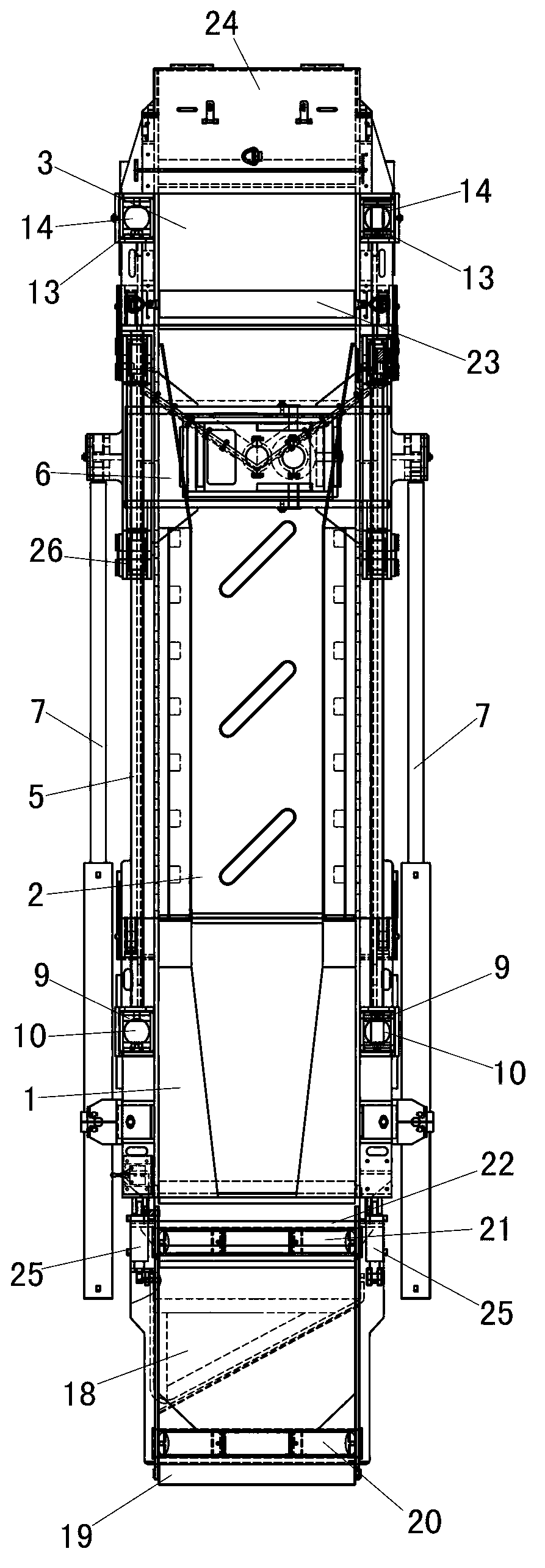
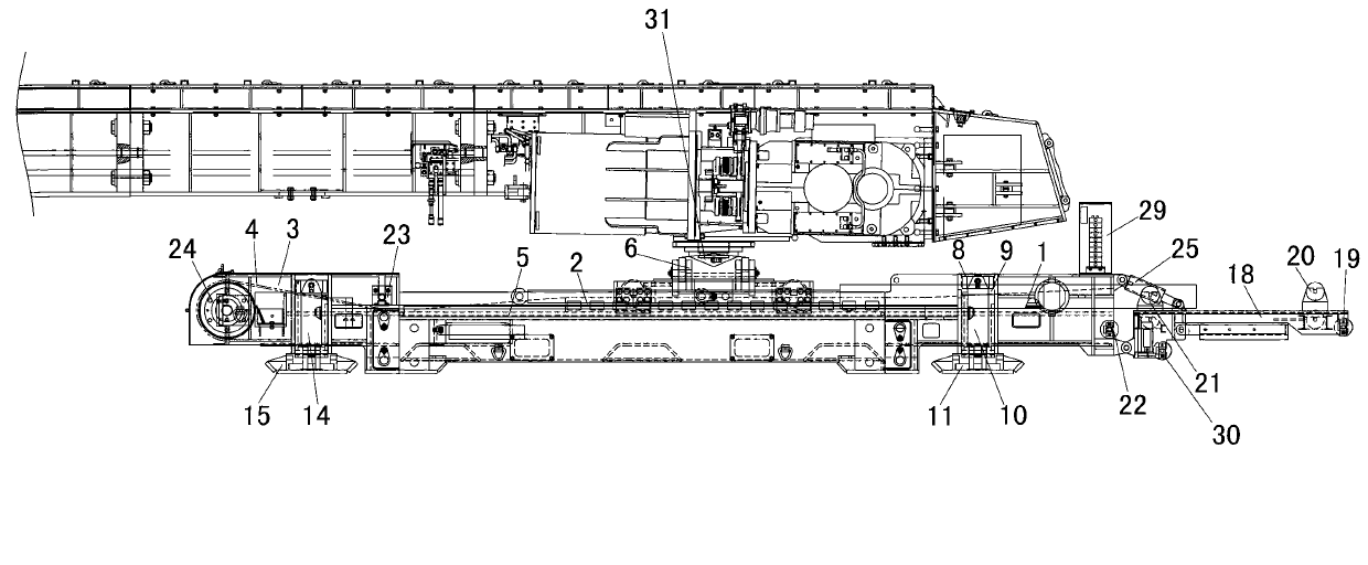
[0040] like Figure 1 to Figure 3 As shown, the hydraulic self-moving tail device of the present invention includes a guide frame 18, a nose 1, a rail 2 and a tail 3 which are sequentially connected together from front to back.

[0041] combine Figure 4 to Figure 6 As shown, the left and right sides of the rear end of the guide frame 18 are respectively hinged with the front ends of the two angle-adjusting cylinders 25 through the pin shaft, and the rear ends of the two angle-adjusting cylinders 25 are respectively connected with the left and right sides of the front end of the machine head 1 through the pin shaft. Right side hinged. One end of the angle-adjusting cylinder 25 connected to the machine head 1 is higher than the other end of the angle-adjusting cylinder 25 connected on the guide frame 18 . Both angle adjustment cylinders 25 are connected with the hydraulic control system 29 through hydraulic pipelines. The hydraulic control system 29 is installed on the top o...


PUM


Abstract

The invention relates to a hydraulic self-moving tail device, which belongs to the technical field of transporters in mines. The hydraulic self-moving tail device comprises a head, a rail and a tail, wherein the head, the rail and the tail are connected in sequence from front to back; a belt of a belt conveyor is installed on the head, the rail and the tail; a track is arranged on the upper surface of the rail; a trolley which can slide back and forth and is connected with a head of a reversed loader together is arranged on the track; the left and right sides of the trolley are respectively and fixedly connected with one end of each pushing cylinder, and the other ends of the two pushing cylinders are respectively and fixedly connected with the left and right sides of the head; the pushing cylinders are connected with a hydraulic control system; and the contractility provided by the two pushing cylinders is greater than the friction force when the reversed loader is pulled forward and less than the friction force when the reversed loader is pushed backward. According to the hydraulic self-moving tail device disclosed by the invention, self movement is realized through mechanized operation and control, so that the tail of the belt conveyor is moved, manual operation is omitted, the work efficiency is high, and the use is safe and convenient.

Description

technical field [0001] The invention relates to a transport device in a mine, in particular to a hydraulic self-moving tail device. Background technique [0002] The belt conveyor connected to the loader on the coal mining face of the coal mine, as the loader advances, the tail of the belt conveyor will move accordingly. The existing mode of moving the tail of the belt conveyor is the mode of pulling with a return column winch. When in use, two sliders need to be set, and at least a winch operator, a hook worker, a signal worker, a security guard and a follower need to be equipped. There are following disadvantages in using this column back winch: [0003] 1. The belt conveyor needs to be pulled by the return column winch every day. It is necessary to repeat a series of tasks such as fixing the slider, unwinding the rope, connecting and fixing the hook head and the belt tail, and putting the warning operation. For a long time, the workload is virtually increased. increase...

Claims


Application Information

Patent Timeline
IPC IPC(8): B65G21/12
Inventor 程东平崔成春宋小辉王兴存
Owner TRIUMPH HEAVY IND
Why Eureka
Try Eureka