

Cooling system for outboard motor
a technology for cooling systems and outboard motors, which is applied in the direction of steam power plants, marine propulsion, vessel construction, etc., can solve the problems of engine dislocation, engine body or engine components distortion, and excessive heat,
- Summary
- Abstract
- Description
- Claims
- Application Information
AI Technical Summary
Benefits of technology
Problems solved by technology
Method used
Image

Examples
Embodiment Construction
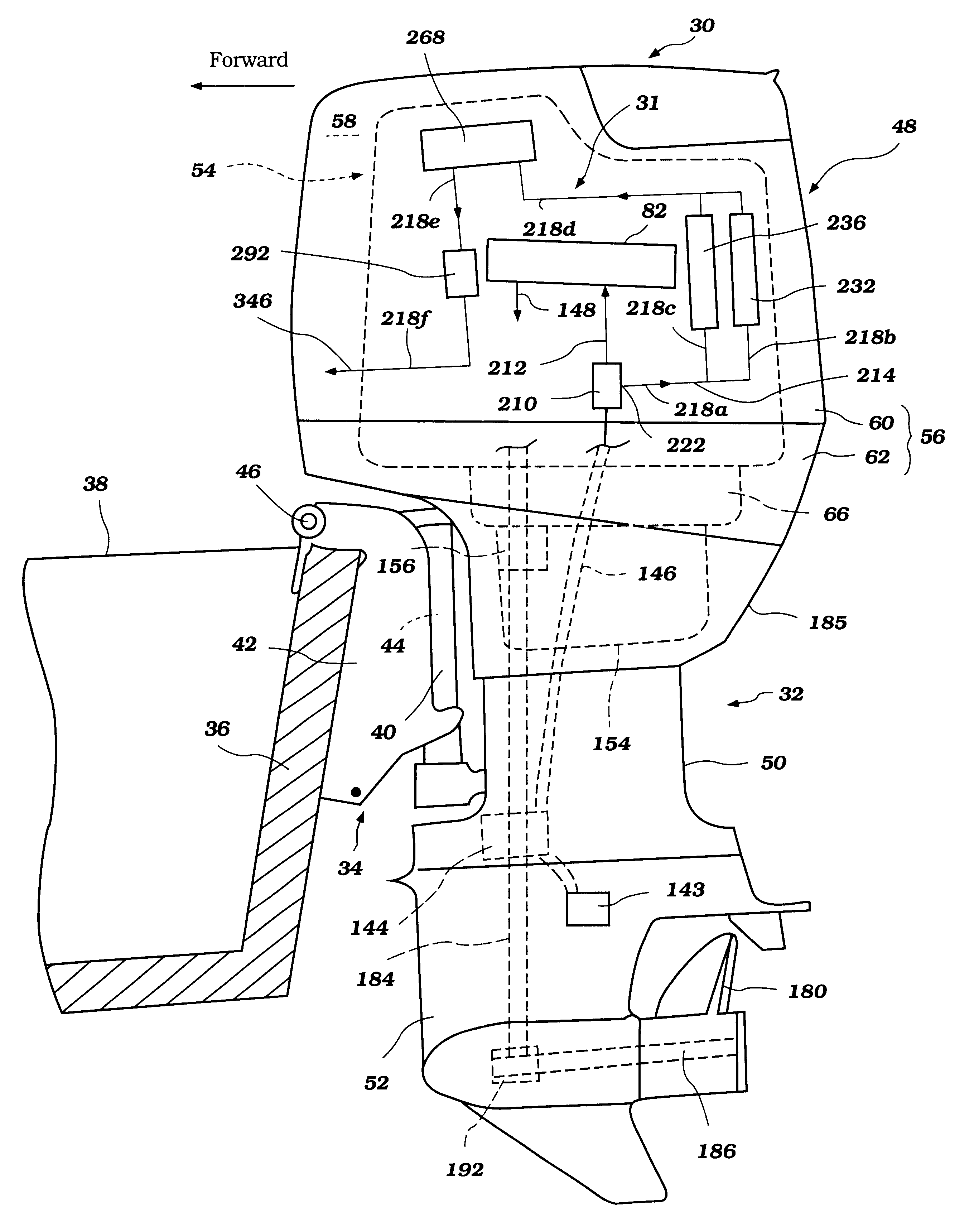
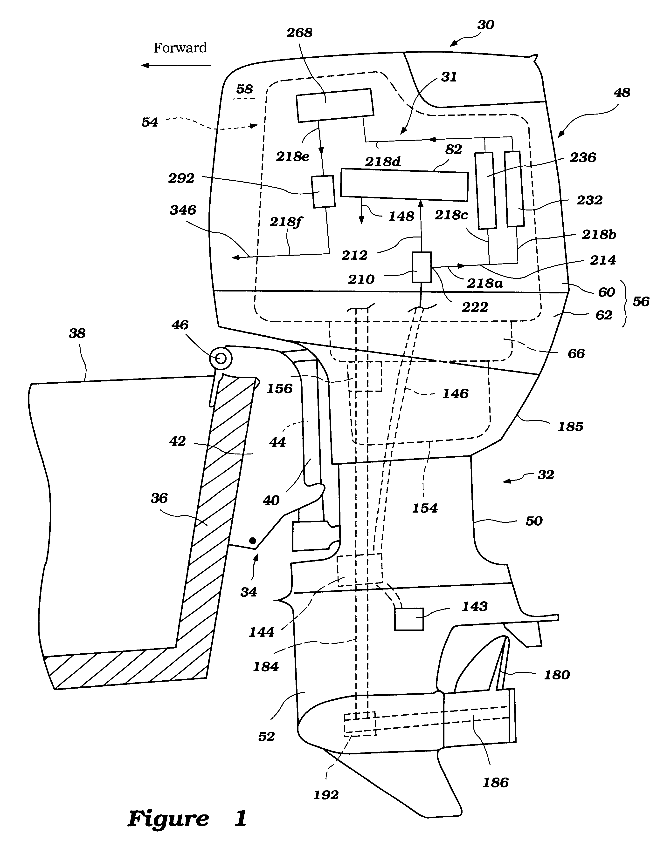
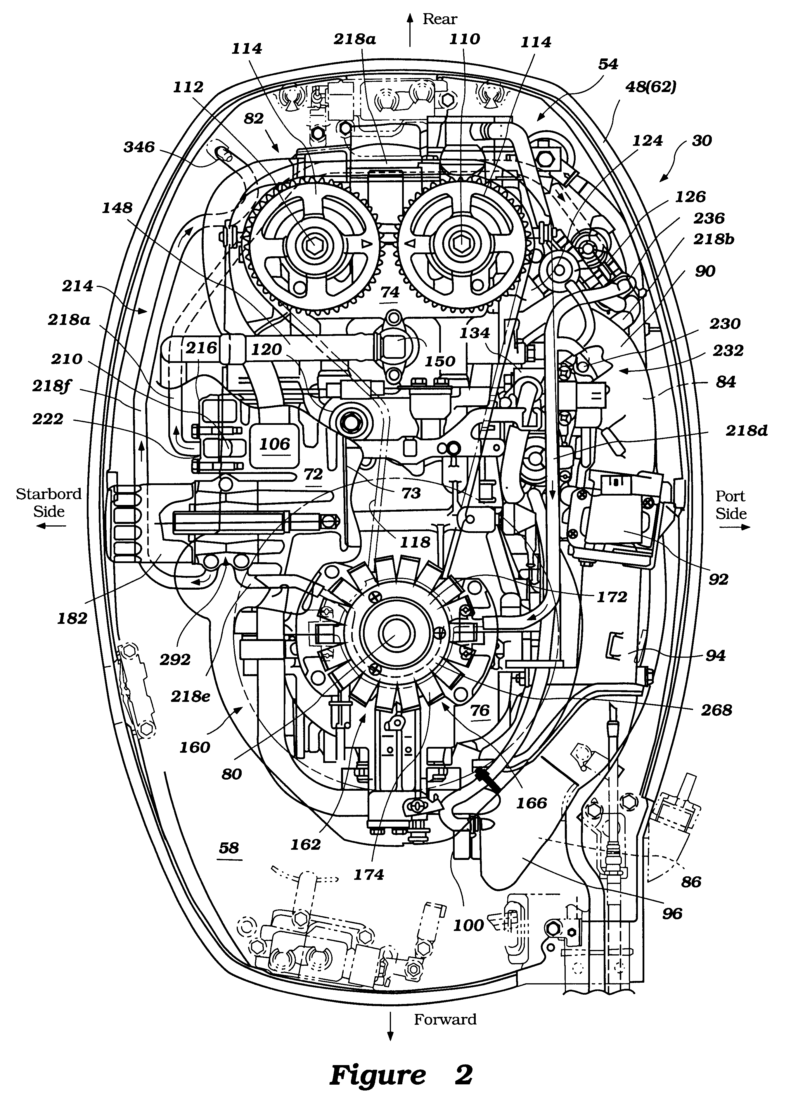
With reference to FIGS. 1-4, an overall construction of an outboard motor 30, which employs a cooling system 31 arranged in accordance with certain features, aspects and advantages of the present invention will be described. In the illustrated arrangement, the outboard motor 30 comprises a drive unit 32 and a bracket assembly 34. The bracket assembly 34 supports the drive unit 32 on a transom 36 of an associated watercraft 38 and places a marine propulsion device in a submerged position with the watercraft 38 resting on the surface of a body of water. The bracket assembly 34 preferably comprises a swivel bracket 40, a clamping bracket 42, a steering shaft 44 and a pivot pin 46.
The steering shaft 44 typically extends through the swivel bracket 40 and is affixed to the drive unit 32. The steering shaft 44 is pivotally journaled for steering movement about a generally vertically-extending steering axis defined within the swivel bracket 40. The clamping bracket 42 comprises a pair of br...
PUM
 Abstract
Description
Claims
Application Information