Locking cable support

Inactive Publication Date: 2003-02-04
ARLINGTON INDS
View PDF10 Cites 15 Cited by
  • Summary
  • Abstract
  • Description
  • Claims
  • Application Information

AI Technical Summary

Benefits of technology

The invention is an improved cable support that provides support for cables similar to that provided by prior art bridle rings but without the several disadvantages inherent in the prior art. Since it is of non-metallic construction, the cable support of this invention reduces the possibility of abrasion occurring to cables held within its ring portion, minimizes the possibility of unwanted magnetic fields interfering with signals running through the cables, and eliminates corrosion. The shape, material of construction, and flexibility of the locking cable support enable it to open wider than prior art metallic bridle rings. As a result of the

Problems solved by technology

As a consequence of the limited size of the gap in prior art bridle rings and the rigid construction, cable bundles do not fit in prior art bridle rings.
The gap in prior art bridle rings is so narrow that cable bundles cannot be fit into them.
When running communication cables with the existing art bridle rings, it is common for the individual cables in the bundle to be bent, twisted, or otherwise damaged as a result of the limited size of the gap, the rigid construction, and the small diameter of the metal rod utilized in constructing the ring.
The metal rod that the bridle ring is constructed from is typically 0.25" in diameter and can disturb the small cables that are typically within Category 5 cable.
Bending and twis

Method used


Image

  • Locking cable support
  • Locking cable support
  • Locking cable support

Examples


Embodiment Construction

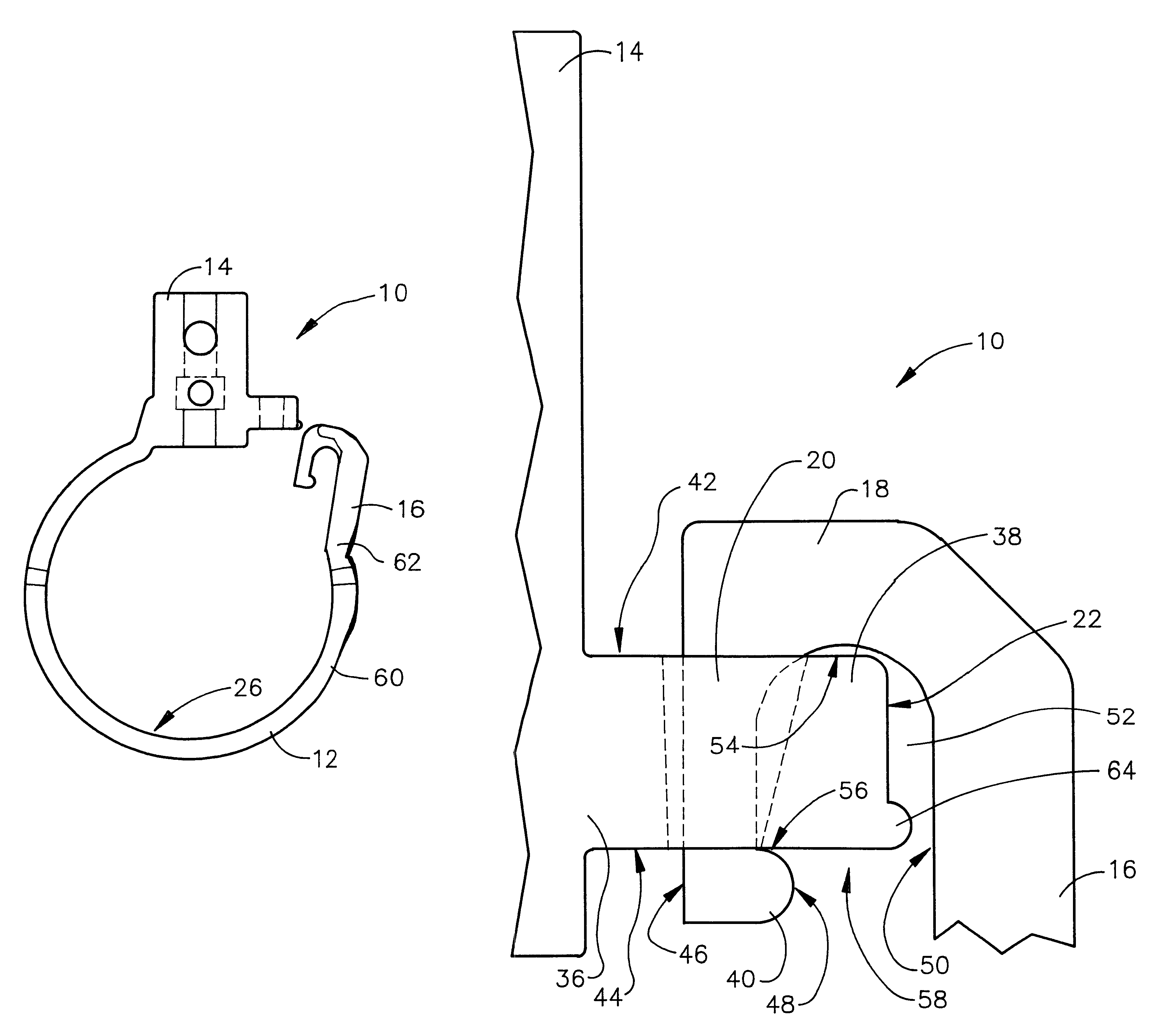
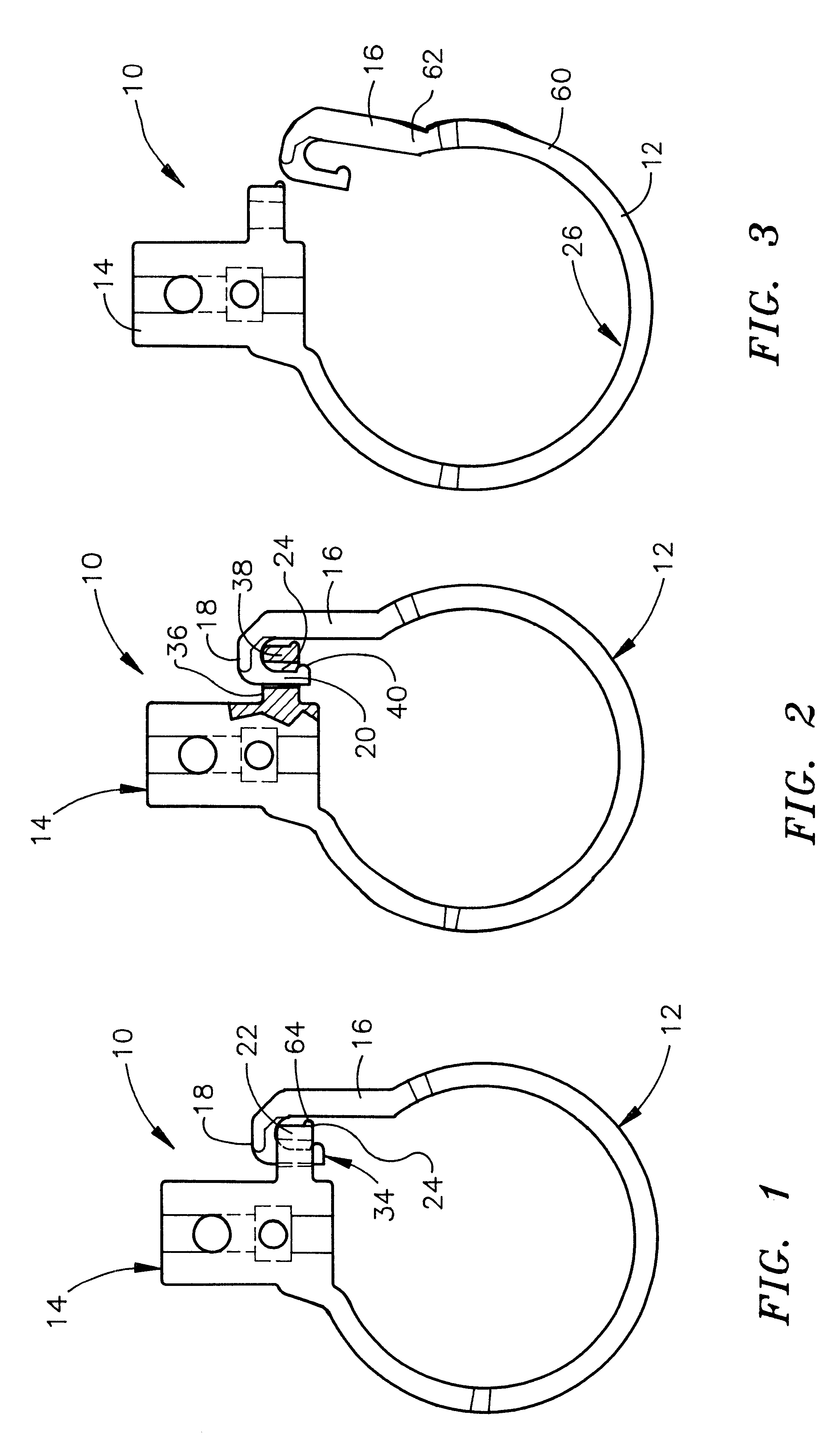
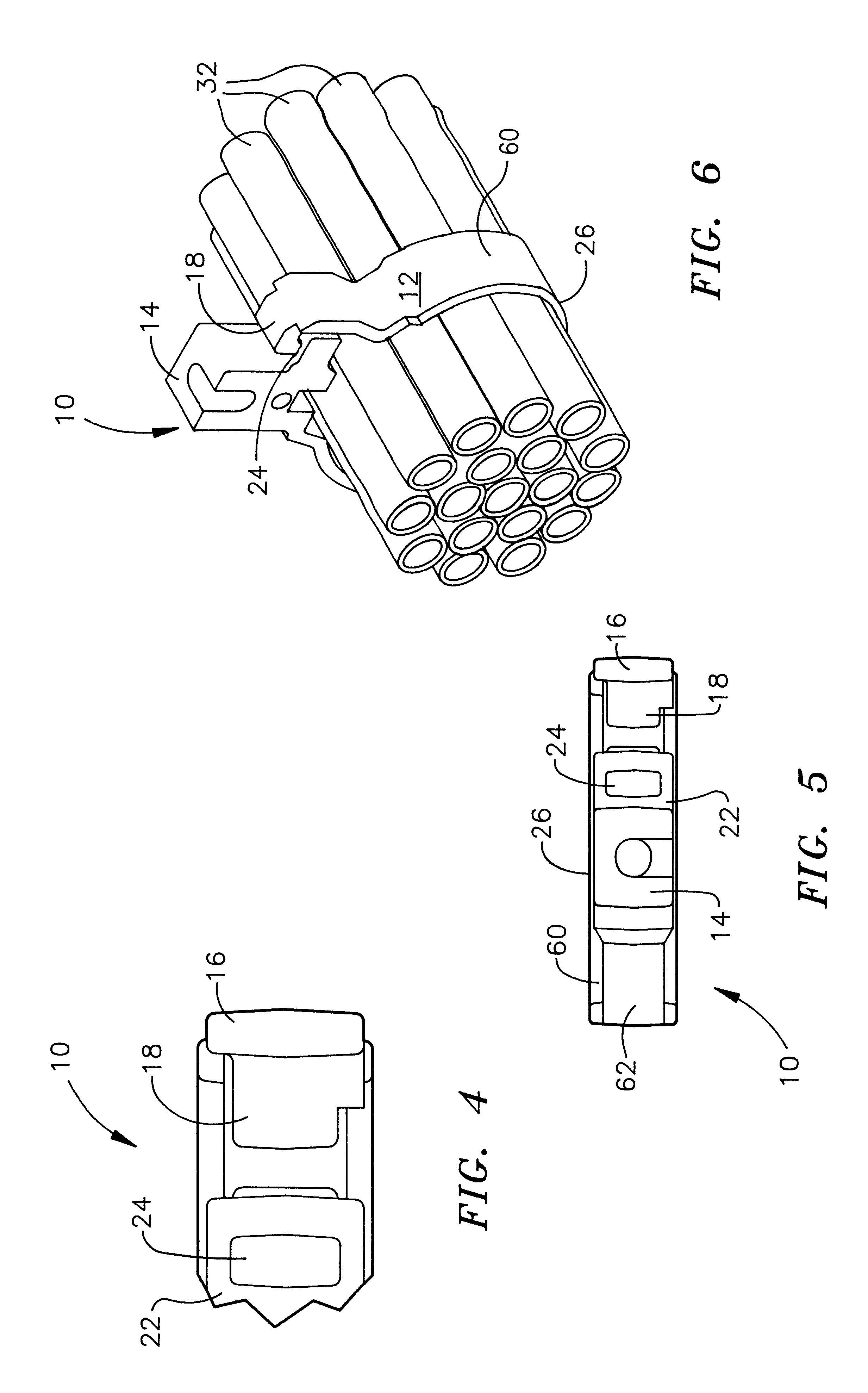
The present invention consists of a locking cable support. Referring to FIG. 1, a plan view of the preferred embodiment in its closed configuration, the locking cable support 10 includes an integral head 14 and ring 12. The ring 12 extends in a circular shape from one side of the head 14 to an end 34 near the opposite side of the head. A leverage arm 16, integral with the end 34 of the ring 12, extends outward from the central axis of the cable support 10 and includes a latch 18 extending toward the head 14. The head may contain a threaded rod (not shown in FIG. 1) to facilitate easy screw-on attachment to a beam clamp or could employ any common techniques for attachment to a beam. An integral head extension 22 extends outwardly from the head 14 toward the leverage arm 16 and latch 18 and includes an integral nub 64 and a latch-receiving pocket 24 (in dashed lines).

FIG. 2 is a plan view of the locking cable support of FIG. 1 in its closed configuration and with a portion of the head...


PUM


Abstract

A locking cable support that reduces potential wire abrasion, minimizes magnetic interference to communication signals, and provides a wide opening feature that permits easy insertion of cables without first twisting them. The shape and flexibility of the improved locking cable support enable it to be opened wider than prior art metallic bridle rings, allowing easier insertion of wires. Non-metallic construction minimizes potential wire abrasion and reduces the possibility of magnetic interference with communication signals. A wide surface in the ring portion provides a comfortable seat for cables with minimal bending of cables between supports.

Description

This invention relates to cable supports and specifically to an improved locking cable support that is of non-metallic construction. Non-metallic construction prevents abrasion of cables held within the cable support, minimizes the possibility of unwanted magnetic fields interfering with signals running through communication cables within the cable support, and eliminates corrosion. The shape and flexibility of the improved cable support enable it to be opened wide, thereby permitting insertion of bundles of cables or individual cables without distorting the cables. The cable support of the present invention includes an improved locking feature whereby the ends of the ring snap together easily and are held more securely than previous versions of the ring.When used in the electrical industry, the term "bridle ring" usually refers to a cable hanger that is constructed from a rod of steel. It is generally a one-piece rod of steel bent into a circular hoop with a connection mechanism, s...

Claims


Application Information

Patent Timeline
IPC IPC(8): F16L3/12F16L3/22F16L3/133F16L3/23
CPCF16L3/133F16L3/233Y10T24/1498Y10T24/45277F16B45/035
Inventor GRETZ, THOMAS J.
Owner ARLINGTON INDS
Why Eureka
Try Eureka