Air-conditioning system for airplane cabin

a technology for air conditioning systems and airplane cabins, applied in the direction of air-treatment apparatus arrangements, applications, light and heating equipment, etc., can solve the problems of ice formation in the prepared fresh air, destroying the surface of the turbine wheel and the turbine nozzle, and extremely dry tapped power unit air

Inactive Publication Date: 2003-02-18
LIEBHERR AEROSPACE LINDENBERG
View PDF7 Cites 53 Cited by
  • Summary
  • Abstract
  • Description
  • Claims
  • Application Information

AI Technical Summary

Problems solved by technology

Dehumidification is necessary primarily in ground operation, however, because in flight, i.e., at high altitudes, the ambient air and thus the tapped power unit air is extremely dry anyway.
This is because residual moisture in the form of fine droplets can destroy the turbine wheel surfaces and the turbine nozzles, since the air in the turbine T almost reaches the speed of sound.
As mentioned in the beginning, ice formation in the prepared fresh air presents a problem.
The bleeding of the fresh air to be prepared directly from the power unit proves to be problematic in the above-described air-conditioning systems.
The drive capacity required for this and the accordingly necessary drive machines are enormous and extremely heavy, however, and this is not compatible with the demands made on an airplane.
However, it is difficult to implement such a system in energy-saving and structurally acceptable manner, particularly in terms of a compact, simple design and with a low weight.
This was unable to assert itself, however.
In particular, two high pressure water extraction circuits must be produced with corresponding weight disadvantages and complex design.
The turbine used for it is also extremely complex because it is divided into two and it is not optimal in terms of efficiency.

Method used


Image

  • Air-conditioning system for airplane cabin
  • Air-conditioning system for airplane cabin
  • Air-conditioning system for airplane cabin

Examples


Embodiment Construction

Further scope of applicability of the present invention will become apparent from the detailed description given hereinafter. However, it should be understood that the detailed description and specific examples, while indicating preferred embodiments of the invention, are given by way of illustration only, since various changes and modifications within the spirit and scope of the invention will become apparent to those skilled in the art from this detailed description.

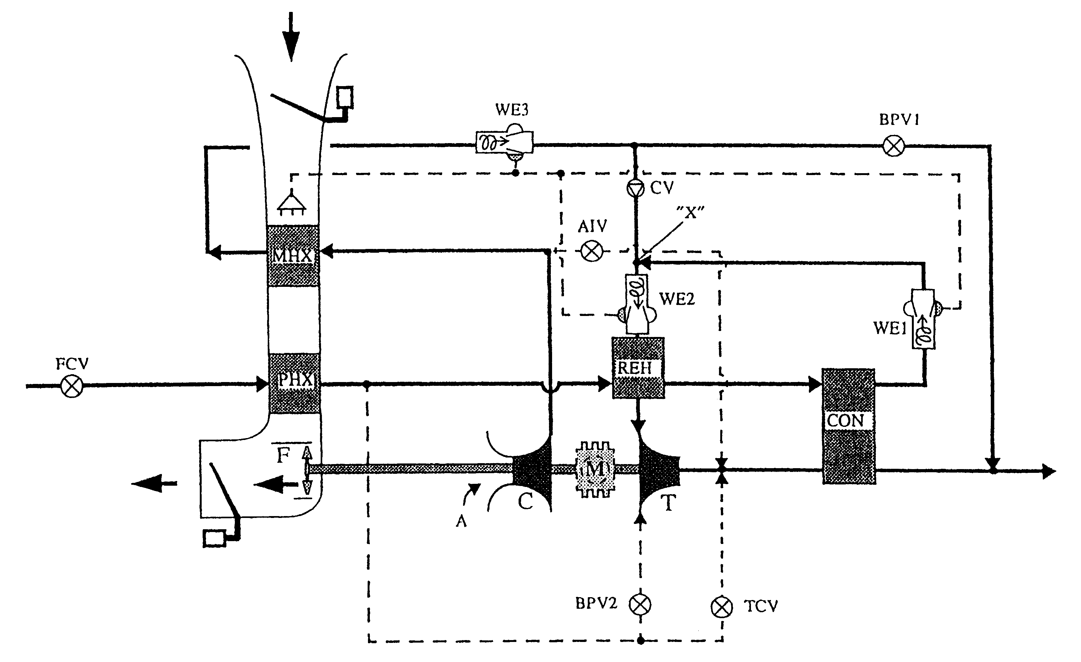
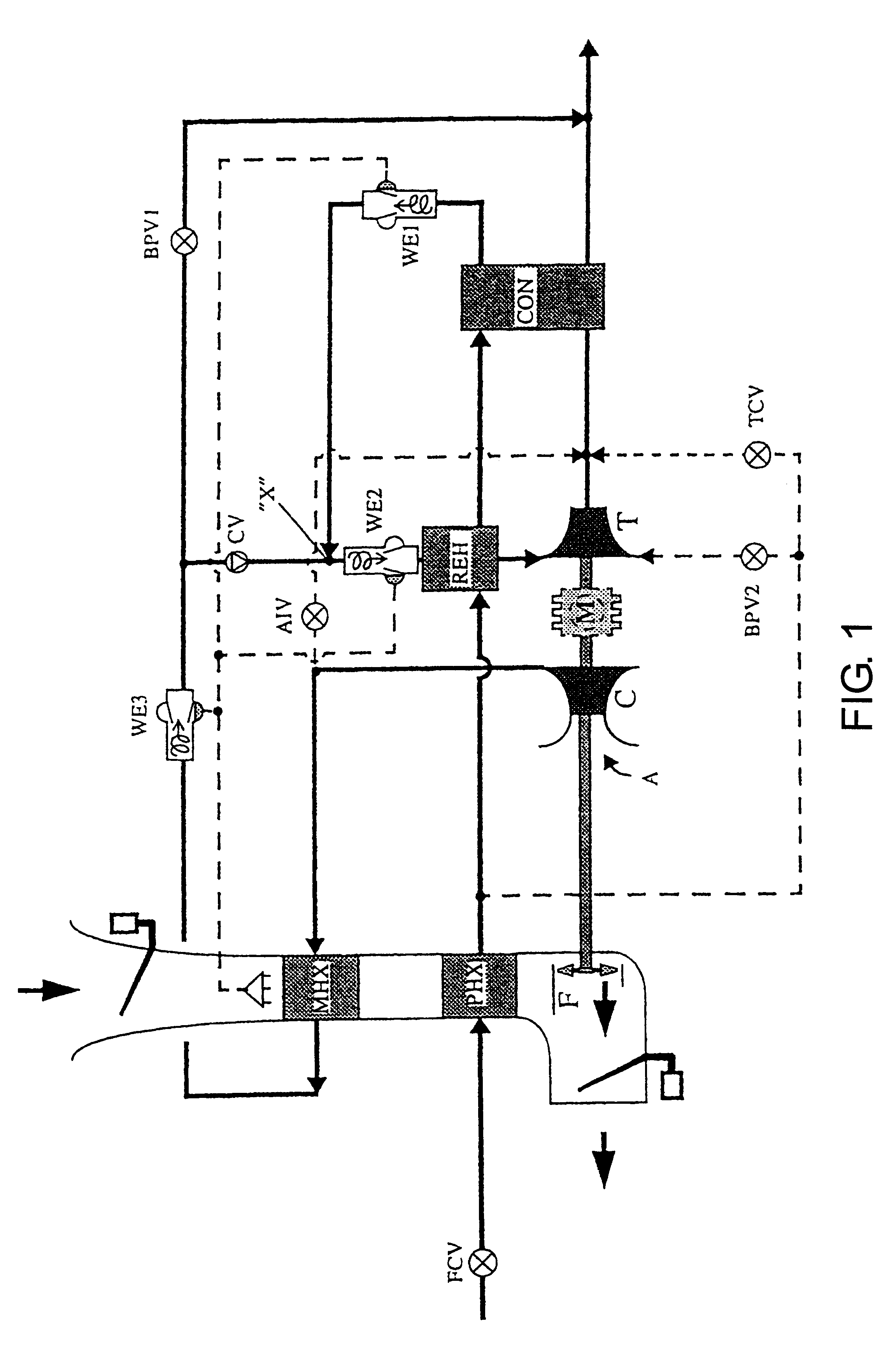
FIG. 1 shows an air-conditioning system that comprises a tapped air circuit and another circuit for air sucked from the surroundings ("ambient air circuit"). The tapped air circuit largely corresponds to the air-conditioning system described using FIG. 4 with respect to the state of the art. However, the tapped airflow is not further compressed after passing the primary heat-exchanger PHX, but rather it is conveyed immediately into the high pressure water extraction circuit. A compression of the tapped airflow is not n...


PUM


Abstract

An air-conditioning system for airplanes is proposed in which a portion of the fresh airflow to be prepared is tapped at high pressure from a power unit and another portion is sucked in from the surroundings. The energy potential of the tapped airflow is utilized to compress the ambient air. The compressed ambient air and the tapped air are mixed into a mixed airflow before the mixed airflow's pressure is expanded in one or more turbine stages (T1, T2). Water is separated from the mixed airflow between the mixing point (X) and the first turbine stage 1 (T1). In order to cool down the tapped airflow to a temperature at which water can be separated at all, the tapped airflow is guided past the entire cooler mixed airflow, preferably in two steps (REH, CON), namely once before the pressure expansion and another time after the pressure expansion of the mixed airflow in the first turbine stage (T1) . In a preferred form of execution, the ambient air is compressed in two steps, in connection with which in each case a compressor wheel (C1, C2) and a turbine wheel (T2, T1) (two-step pressure expansion) are mounted together on a shaft.

Description

1. Field of the InventionThe invention relates to an air-conditioning system for preparing pressurized air for the air-conditioning of a space, in particular for the air-conditioning of airplane cabins, and a corresponding process.2. Prior ArtThe fresh air for the air-conditioning of airplane cabins is usually prepared from the air tapped under high pressure and at high temperature from the power unit, referred to as bleed. The air-conditioning systems draw the cooling capacity required for the preparation from the pressure and temperature potential of the precompressed power unit air. The bleed is cooled off during the course of the fresh air preparation process and its pressure drops to the cabin pressure of 1 bar in ground operation or roughly 0.8 bar in flight. During the process of fresh air preparation the air is also dehumidified in order to prevent an icing of individual components of the air-conditioning system and ice crystal formation in the fresh air to be prepared. Dehu...

Claims


Application Information

Patent Timeline
Patent Type & Authority Patents(United States)
IPC IPC(8): B64D13/06B64D13/00F25B9/00
CPCB64D13/06B64D2013/0648Y02T50/56F05B2220/50F25B9/004B64D2013/0662Y02T50/50
Inventor SAUTERLEUTE, ALFRED
Owner LIEBHERR AEROSPACE LINDENBERG
Why Eureka
Try Eureka