Microfluidic actuator

a microfluidic actuator and actuator technology, applied in the direction of positive displacement liquid engines, machines/engines, laboratory glassware, etc., can solve the problems of inability to integrate devices into a complex microfluidic system, inability to perform this type of microfluidic sample processing technology, and the manufacturing cost of such a device must be extremely low, so as to achieve easy preparation and low cost

Inactive Publication Date: 2003-02-18
IND TECH RES INST
View PDF14 Cites 311 Cited by
  • Summary
  • Abstract
  • Description
  • Claims
  • Application Information

AI Technical Summary

Benefits of technology

Another objective of this invention is to provide a microfluidi

Problems solved by technology

Although such pumps to date have shown excellent performance as discrete devices, often the processes for fabricating these pumps and valves are so unique that the devices cannot be integrated into a complex microfluidic system.
Miniature analytical analysis systems, however, are demanding pumps and valves that are relatively

Method used


Image

  • Microfluidic actuator
  • Microfluidic actuator
  • Microfluidic actuator

Examples


embodiment i

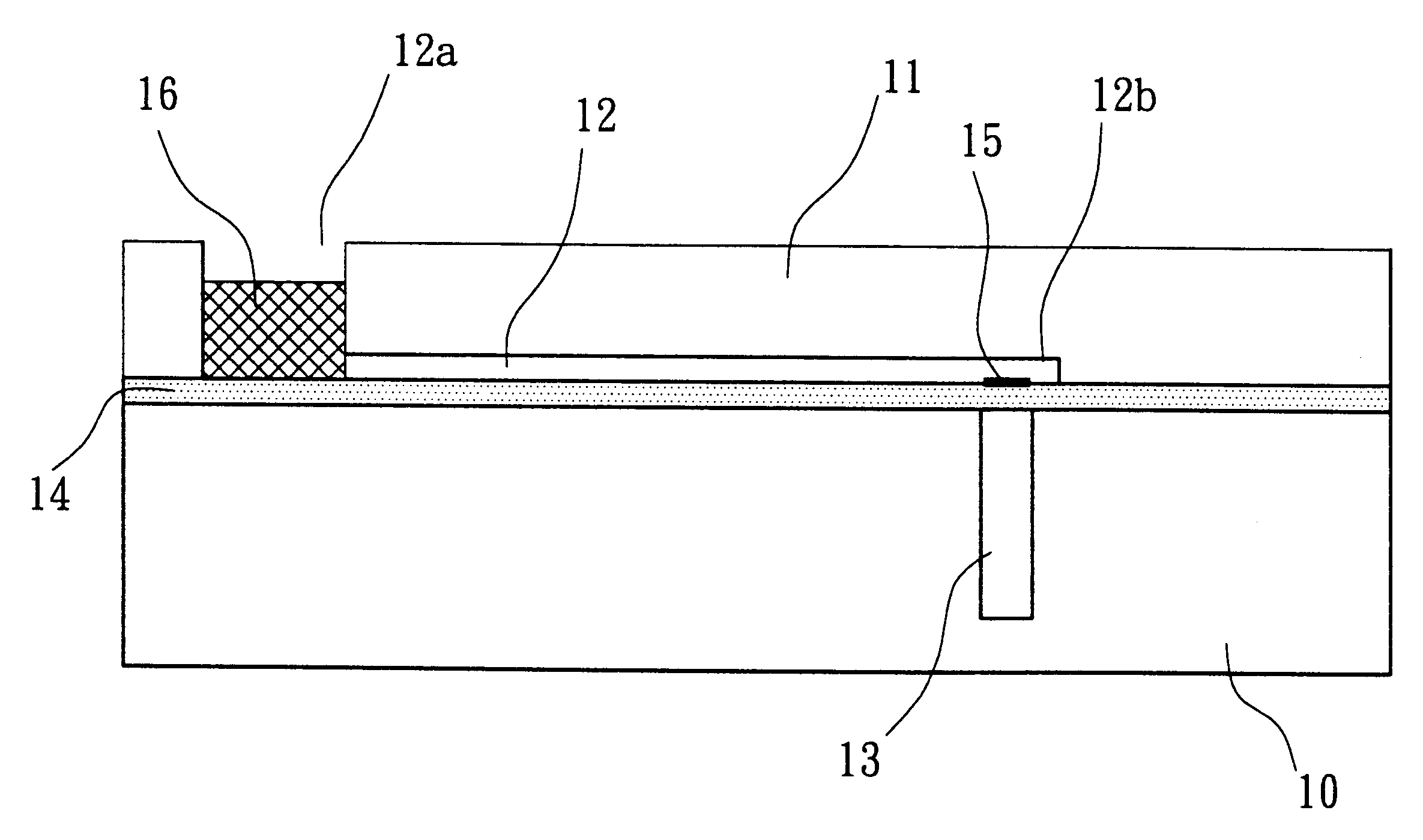
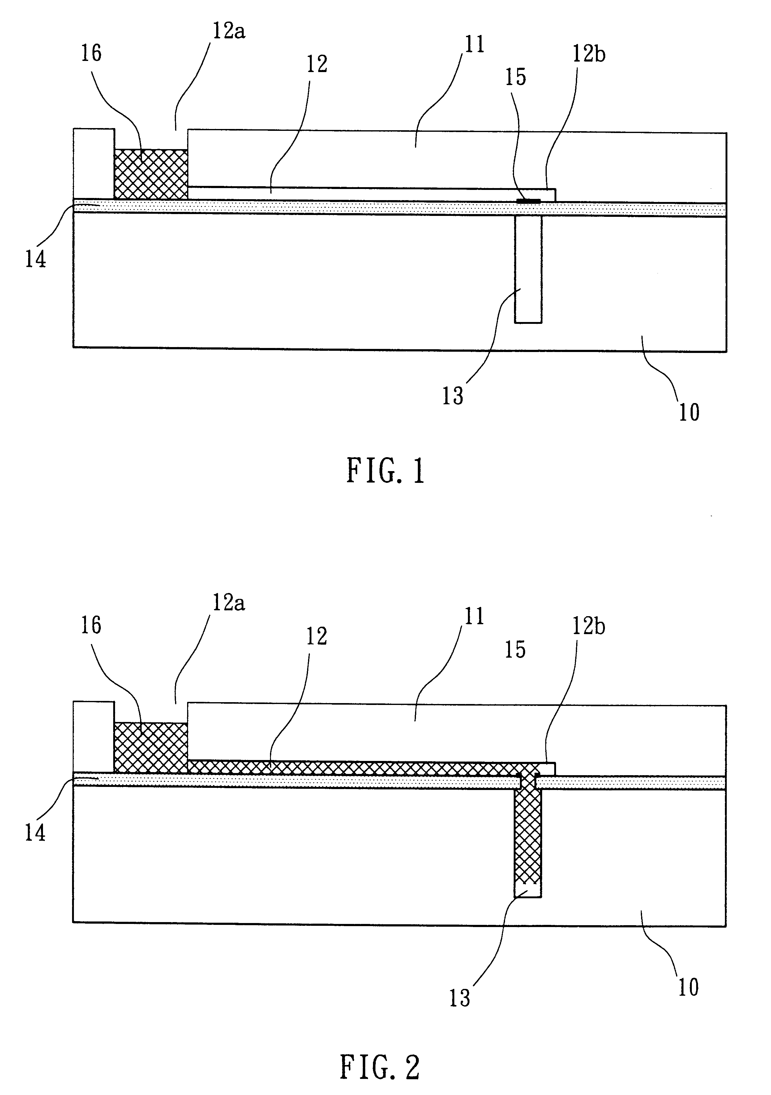
pertains to a microfluid pumping mechanism employing the microfluidic actuator of this invention. FIG. 1 shows the cross sectional view of a microfluid pumping mechanism employing the microfluidic actuator of this invention prior to actuation and FIG. 2 shows its cross sectional view after actuation. As shown in FIGS. 1 and 2, the microfluid pumping mechanism comprises a bottom substrate 10 and an upper substrate 11, a microfluid channel 12 inside said upper substrate 11, a vacuum chamber 13 under said microfluid channel 12, a diaphragm 14 sealing said vacuum chamber 13, and a thin film resistor 15. 16 represents fluid filled into the microfluid channel 12. As shown in FIG. 1, the microchannel 12 has a sealed end 12b and an open end 12a and the vacuum chamber 13 is positioned adjacent to the sealed end 12a of the microchannel 12. Fluid 16, such as a liquid, is filled into the open end 12a of the microchannel 12. The open end 12a forms a reservoir for the fluid 16.

The vacuum chamber ...

embodiment ii

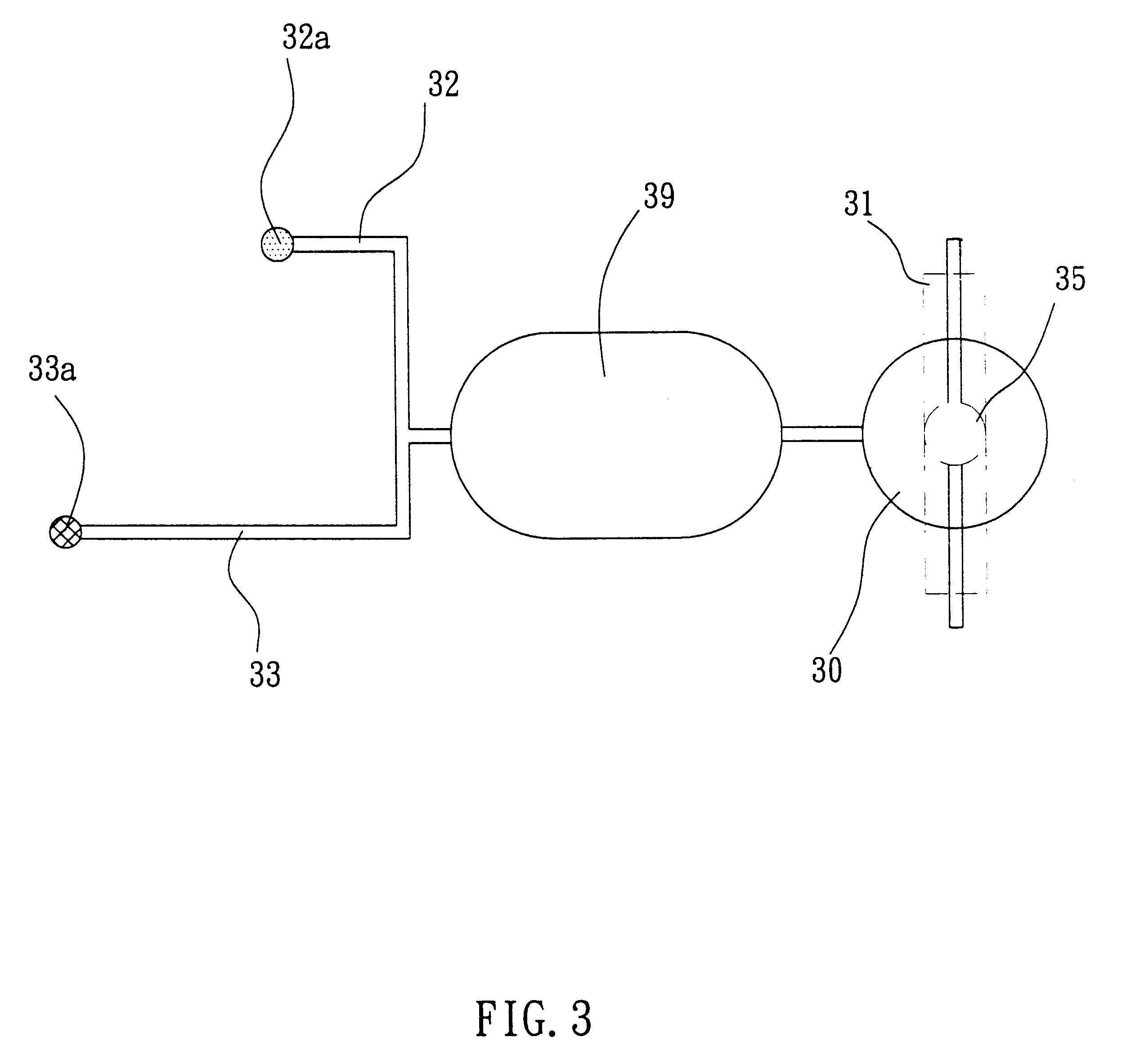
Embodiment II discloses a mechanism for proportionally mixing microfluidic samples using the invented microfluidic actuator. The microfluid mixing mechanism of this embodiment comprises in general a vacuum chamber 31, a mixing chamber 39 and at least 2 microchannels 32 and 33 connected to the mixing chamber 39, allowing liquid samples to flow into the mixing chamber 39. A schematic of one such proportional mixing system is shown in FIG. 3.

As shown in FIG. 3, the microfluid mixing mechanism also comprises an air reservoir 30 connected to the mixing chamber 39, a thin diaphragm (not shown in FIG. 3) separating the air reservoir 30 and the vacuum chamber 31, a thin film resistor 35 positioned on the this diaphragm, and two sample inlets of reservoirs 32a and 33a for filling sample liquids into the microchannels 32 and 33.

Before actuating the microfluidic actuator of this invention, sample liquids are added into the sample inlets 32a and 33a and fill the inlets 32a and 33a and a portion...


PUM


Abstract

A simple microfluidic actuator includes a sealed vacuum chamber actuated by providing a current to a thin film heater, which in turn weakens and, under the atmospheric pressure differential, breaks a diaphragm sealing said vacuum chamber whereby the vacuum inside said chamber is released. By applying the microfluidic actuator to a microfluidic network the resulting pressure differential can be used to generate a pumping force with the microfluidic network. The chamber may be prepared in a silicon, glass, or plastic substrate. The diaphragm may be a metallic gas-impermeable film. A releasing member comprising a thin-film metallic heater is then microfabricated on the diaphragm. The assembly so prepared may be bonded to a glass or plastic substrate that contains a network of microchannels. The microfluidic actuator is suited for a microfluidic platform in generating driving powers for operations including pumping, metering, mixing and valving of liquid samples.

Description

The present invention relates to a microfluidic actuator, especially to an actuator that generates pumping force to a microfluid with a vacuum chamber.Miniature pumps and valves have been a topic of great interest in the past 10 years. Many different pump and valve designs have been implemented by micromachining of silicon and glass substrates. Pumps and valves with pneumatic, thermal-pneumatic, piezoelectric, thermal-electric, shape memory alloy, and a variety of other actuation mechanisms have been realized with this technology. Although such pumps to date have shown excellent performance as discrete devices, often the processes for fabricating these pumps and valves are so unique that the devices cannot be integrated into a complex microfluidic system. Recently, paraffin actuated valves, and hydrogel actuated valves are being developed on the way to a more complex microfluidic platform.Miniature analytical analysis systems, however, are demanding pumps and valves that are relativ...

Claims


Application Information

Patent Timeline
IPC IPC(8): B01L3/00F04F3/00F04B19/00
CPCB01L3/50273F04F3/00F04B19/006B01L2300/0816B01L2400/049B01L2400/0683B01L2400/0677Y10T137/0396Y10T137/2224
Inventor WEBSTER, JAMES RUSSELL
Owner IND TECH RES INST
Why Eureka
Try Eureka