Electric power distributor for use in motor vehicle

a technology for electric power distributors and motor vehicles, which is applied in the direction of electrical apparatus casings/cabinets/drawers, semiconductor/solid-state device details, instruments, etc., can solve the problems of difficult heat release of semiconductor switching elements, high probability, and other circuit elements on the same control circuit board may be subjected to adverse effects of heated semiconductor switching elements

Inactive Publication Date: 2003-02-18
AUTONETWORKS TECH LTD +2
View PDF6 Cites 62 Cited by
  • Summary
  • Abstract
  • Description
  • Claims
  • Application Information

AI Technical Summary

Benefits of technology

It is another object of the present invention to provide an electric power distributor for use in a motor vehicle that enables to suppress a rise of an ambient temperature in a housing with a simplified construction while cooling semiconductor operative elements.

Problems solved by technology

This arrangement makes it difficult to release heat of the semiconductor switching elements, namely, to cool the semiconductor switching elements.
In a worse case, it is highly likely that other circuit elements on the same control circuit board may be subjected to adverse affect of the heated semiconductor switching elements.
Mounting such semiconductor switching elements on the control circuit board without any measures is not desirable as mentioned above.
The above arrangement, however, fails to effectively suppress a rise of an ambient temperature in the housing in the case where the air inside the housing is heated resulting from the heated semiconductor switching elements, although the arrangement is effective in lowering the temperature of the semiconductor switching elements themselves by the heat releasing member to some extent.
Therefore, heat inside the housing is not easily released outside once heat is generated in the housing.
It is highly likely that a rise of an ambient temperature in the housing may adversely affect performance of other electronic devices, especially, a device of a low heat resistance, in the housing.

Method used


Image

  • Electric power distributor for use in motor vehicle
  • Electric power distributor for use in motor vehicle
  • Electric power distributor for use in motor vehicle

Examples


Embodiment Construction

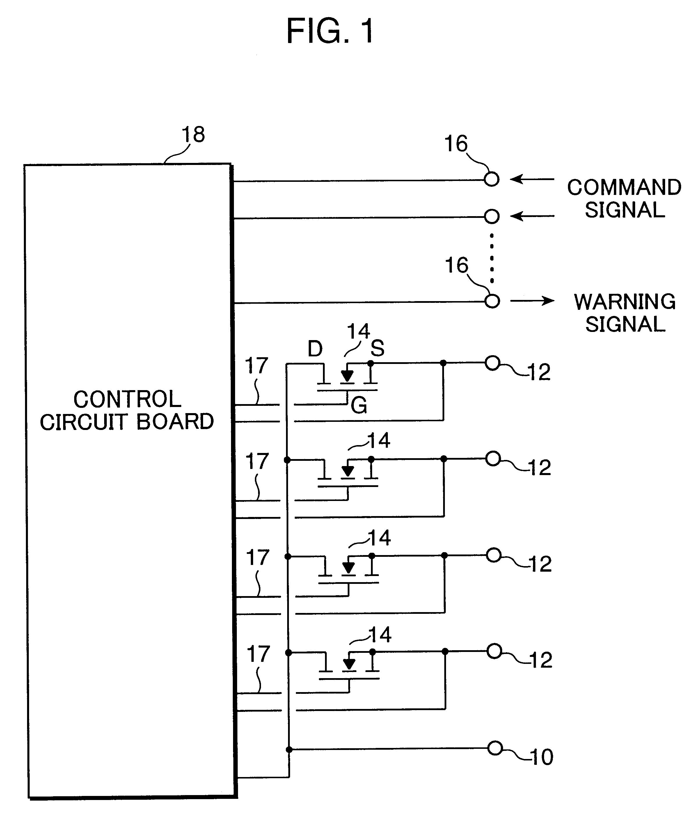
A preferred embodiment of the invention is described with reference to the accompanying drawings. First, a circuit configuration of an electric power distributor for use in a motor vehicle according to an embodiment of this invention is described with reference to FIG. 1.

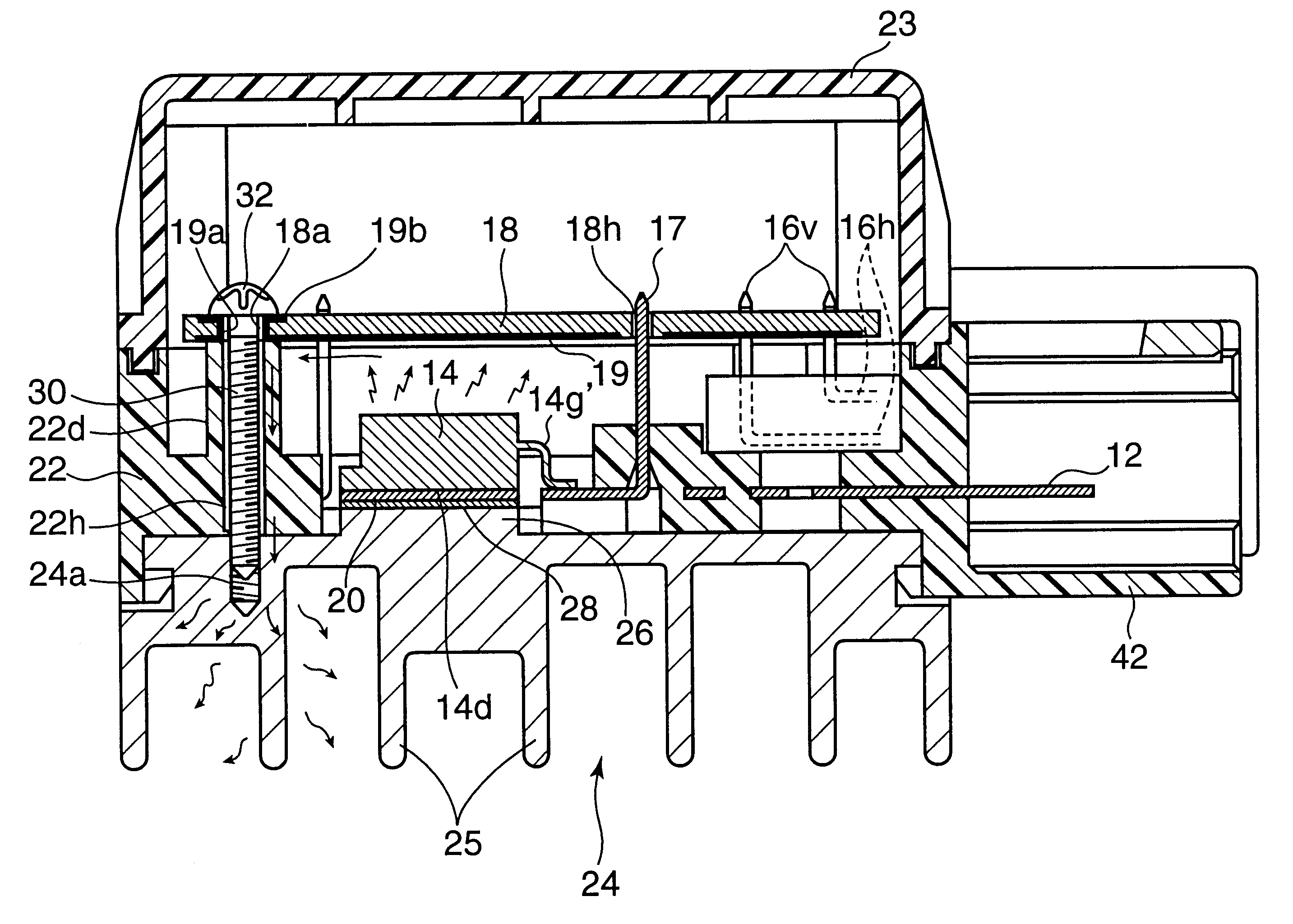
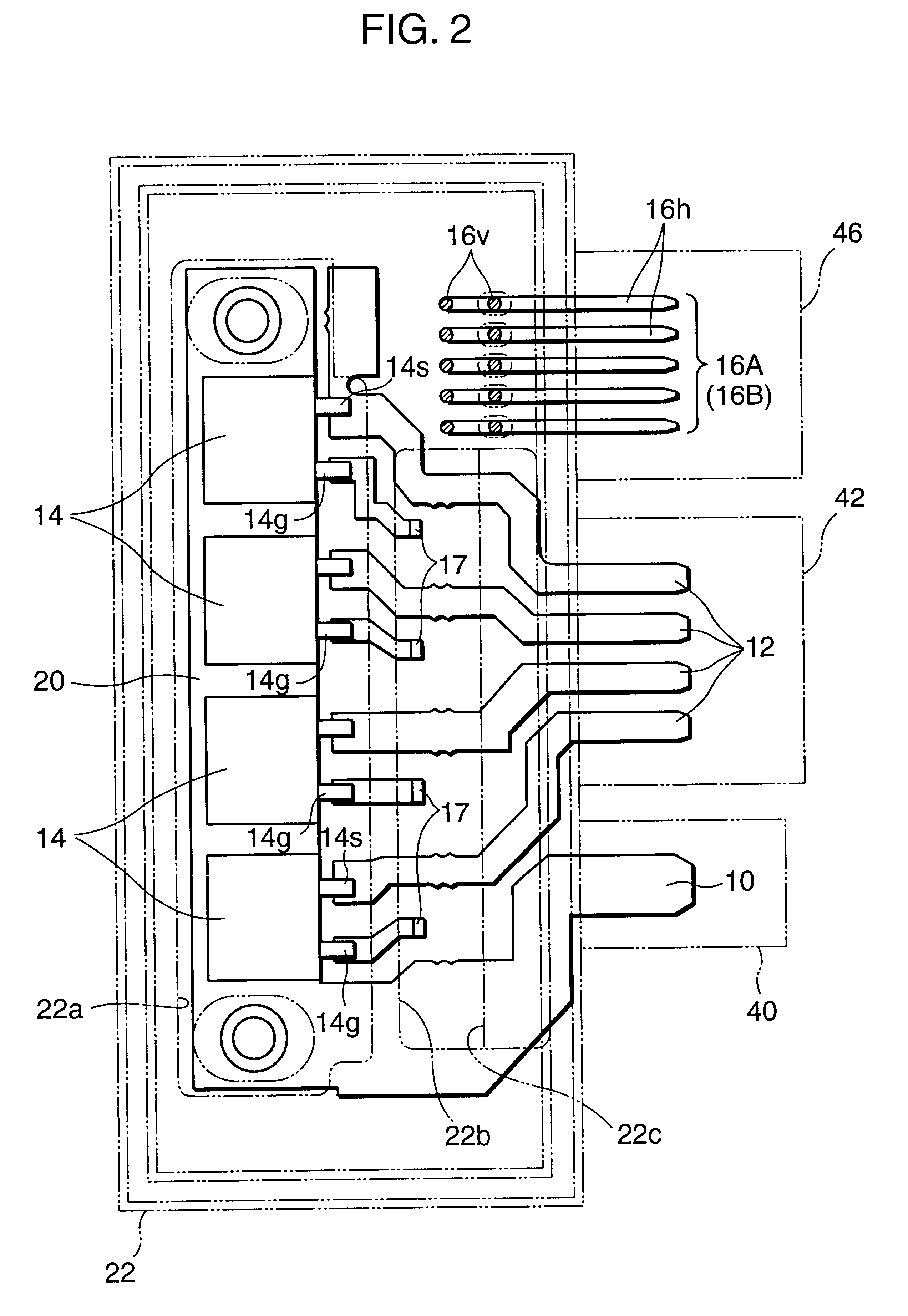
The power distributor comprises one input terminal 10 connected to a battery of the motor vehicle, and a number of output terminals 12 (in FIG. 1, four output terminals). Semiconductor switching elements or semiconductor operative elements 14 (in FIG. 1, power MOSFETs, hereafter simply referred to as "FETs") are provided each between the corresponding output terminal 12 and the input terminal 10. Specifically, a drain D of each FET 14 serving as an input terminal is connected to the input terminal 10, and a source S thereof serving as an output terminal is connected to the corresponding one of the output terminals 12.

A gate G of each FET 14 is connected to a control circuit on a control circuit board 18. In this emb...


PUM


Abstract

An electric power distributor mountable on a motor vehicle for distributing power from a power source installed in the motor vehicle to a plurality of electric load units equipped in the vehicle has a plurality of semiconductor operative elements which are incorporated in a power supply circuit from the power source to the electric load units; a control circuit board incorporated with a control circuit for controlling an operation of the semiconductor operative elements; a housing for encasing the semiconductor operative elements and the control circuit board therein; and a heat releasing member provided on an outer surface of the housing to release heat transferred from the semiconductor operative elements outside of the housing. The control circuit board is arranged at such a position as to be mounted over the semiconductor operative elements from a side of the housing opposite to the mounted side of the heat releasing member with respect to the semiconductor operative elements, and is formed with a heat transfer layer on a side of the control circuit board as opposed to the semiconductor operative elements. The heat transfer layer and the heat releasing member are connected by a heat transfer member.

Description

1. Field of the InventionThis invention relates to an electric power distributor for use in a motor vehicle adapted to distribute electric power supplied from a power source such as a battery incorporated in the motor vehicle to a plurality of electric load units equipped in the motor vehicle.2. Description of the Related ArtHeretofore, there has been known an electric connecting box, as a device for distributing electric power supplied from a power source incorporated in a motor vehicle to a plurality of electric load units equipped in the vehicle. The electric connecting box is constructed in such a manner that a number of substrates each mounted with a bus bar are placed one over another to form a distributing circuit, and various elements such as a fuse and a relay switch are provided on the circuit.Recently, an electric power distributor has been developed to make such an electric connecting box smaller and to accomplish a high-speeding switching control. Such an electric power...

Claims


Application Information

Patent Timeline
Patent Type & Authority Patents(United States)
IPC IPC(8): B60R16/02B60R16/023H01L23/36H05K7/20
CPCB60R16/0238H01L2924/0002H01L2924/00
Inventor YAMANE, SHIGEKI
Owner AUTONETWORKS TECH LTD
Why Eureka
Try Eureka