Methods and apparatus for forming solder balls

a technology of soldering balls and methods, applied in the field of electric circuitry, can solve the problems of failure to form the desired electrical connection, uneven size of solder balls, and slight alteration of the volume and position of each solder ball

Inactive Publication Date: 2003-02-25
MICRON TECH INC
View PDF3 Cites 28 Cited by
  • Summary
  • Abstract
  • Description
  • Claims
  • Application Information

AI Technical Summary

Problems solved by technology

If the height of the solder balls is not uniform, the smaller balls may fail to wet, i.e., adhere, to either the circuit component or the substrate, thus causing the failed formation of the desired electrical connection.
First, the holes in a stencil should be of uniform size and volume, otherwise the solder balls will not be of uniform size.
Second, if a flexible squeegee, such as a rubber squeegee, is used, the squeegee tends to "scoop out" a small portion of the solder paste near the top of each hole in the stencil because the flexible material tends to flex downwardly into each hole.
Third, some of the solder paste tends to stick to the walls of the holes of the stencil.
While the holes formed in this manner tend to be quite uniform, chemically etched stencils unfortunately tend to have holes bordered by small cusps.
Nonetheless, laser cut holes will retain some solder paste and eventually become plugged as well.
Although relatively inflexible squeegees solve the problem of "scoop out," such inflexible squeegees tend to stretch the stencil, thus slightly altering the volume and position of each hole and, eventually, rendering the stencil useless.

Method used


Image

  • Methods and apparatus for forming solder balls
  • Methods and apparatus for forming solder balls
  • Methods and apparatus for forming solder balls

Examples


Embodiment Construction

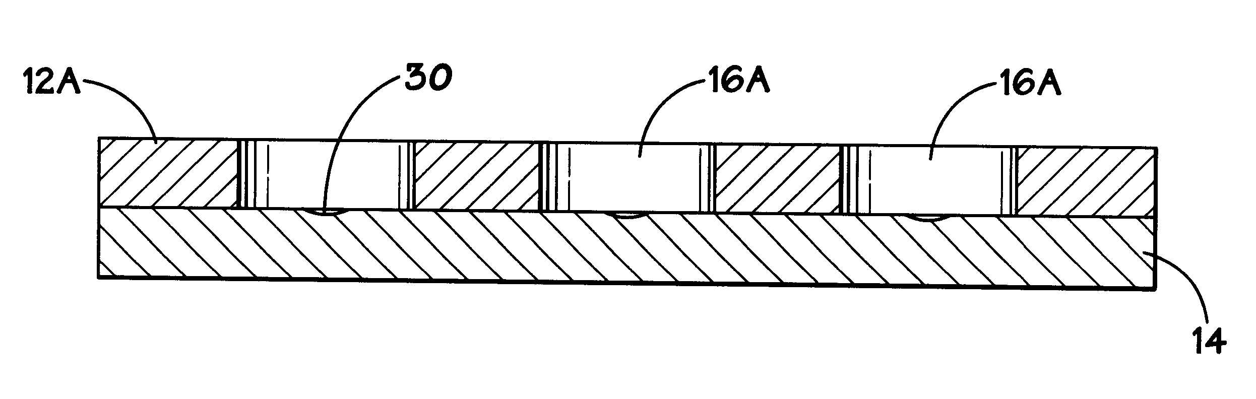
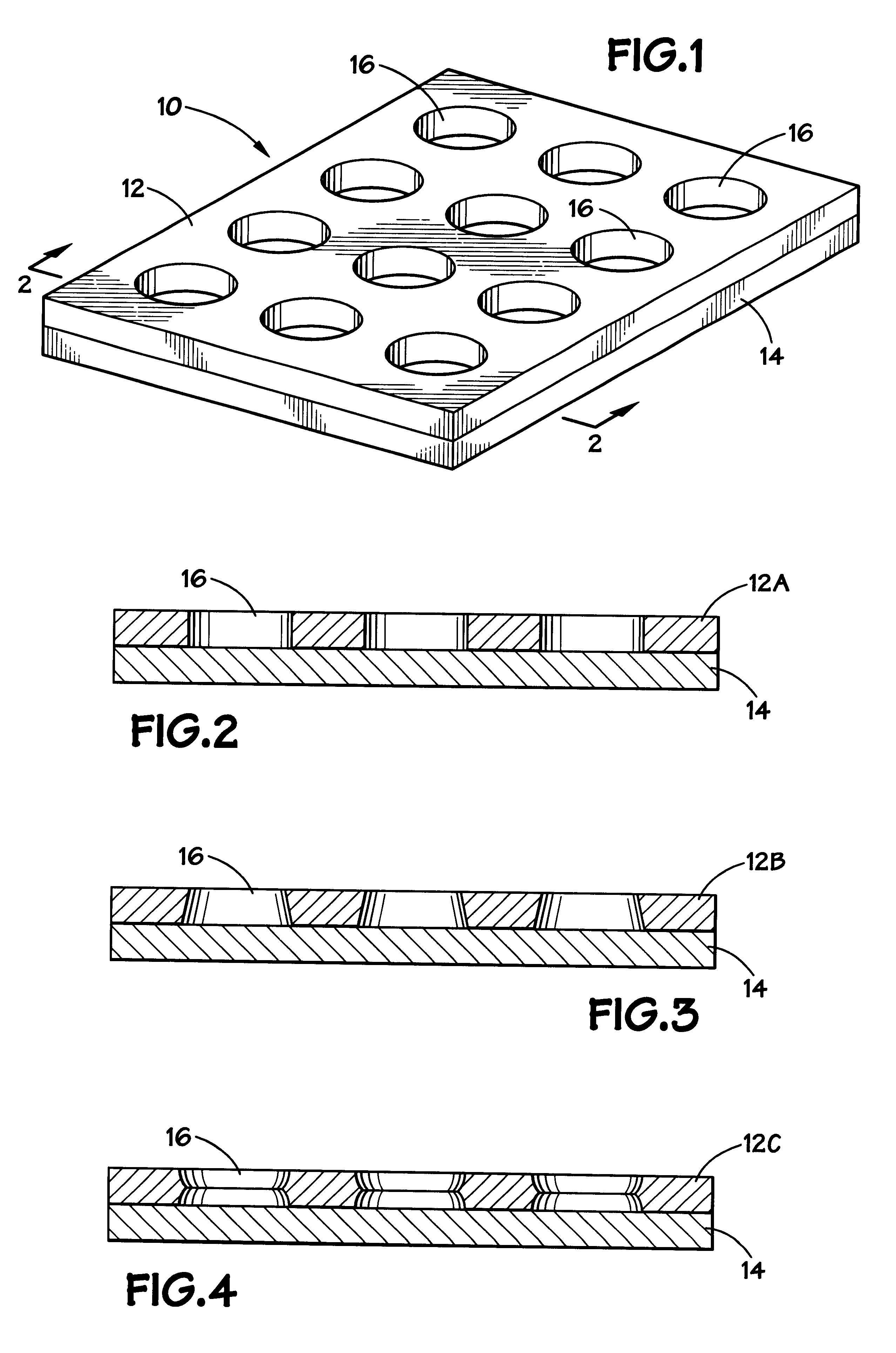
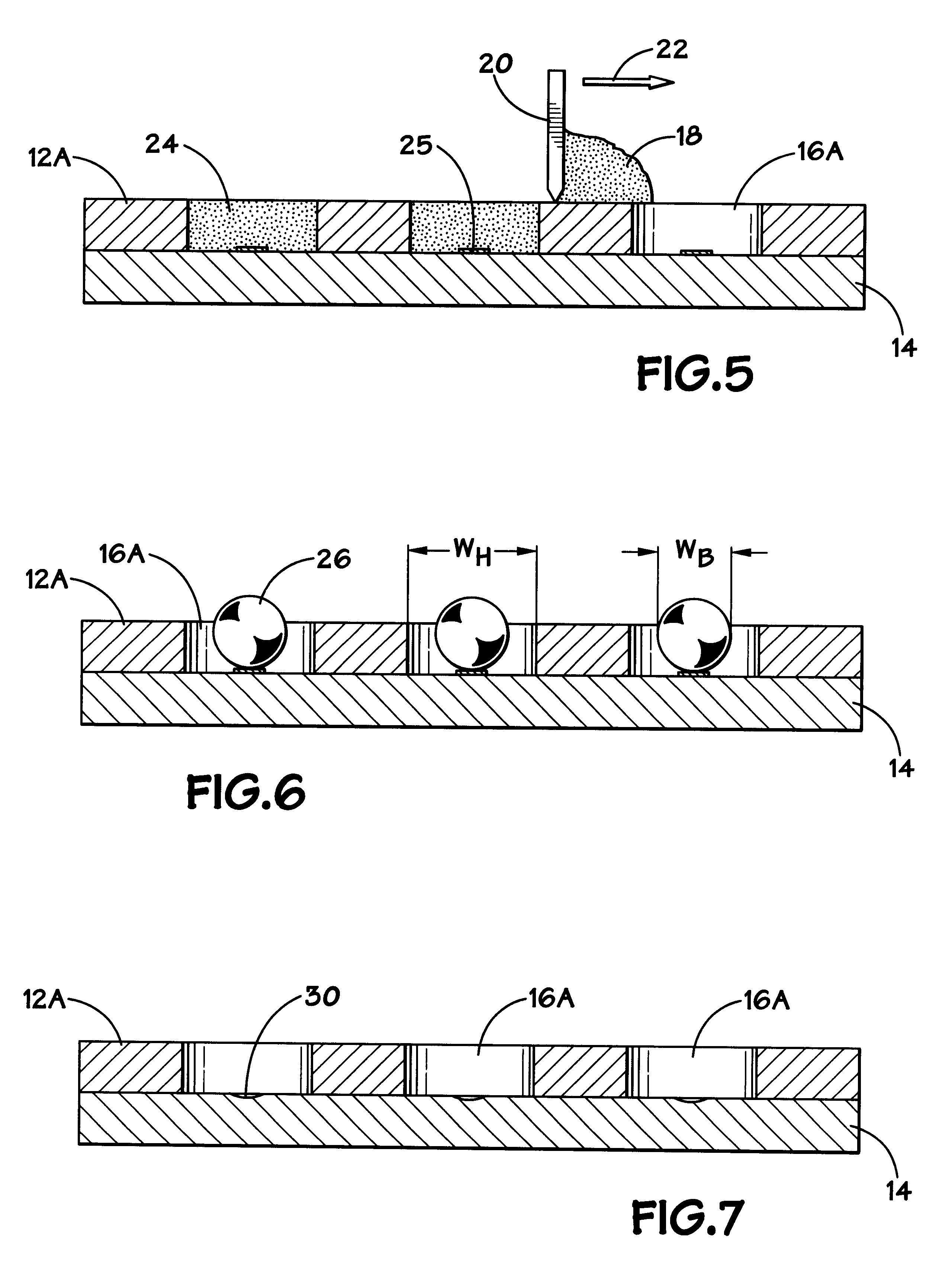
Turning now to the drawings, and referring initially to FIG. 1, an apparatus for forming solder balls is illustrated and generally designated by the reference numeral 10. The apparatus includes a stencil 12 and a substrate 14. The stencil 12 includes a plurality of holes 16 formed therethrough. Unlike the conventional techniques for forming solder balls discussed above, the stencil 12 is disposed on the substrate 14 and it is not removed from the substrate 14 prior to solder ball formation. Rather, as discussed in detail below, solder paste is disposed in the holes 16 of the stencil 12, and the apparatus 10 is heated to melt and reflow the solder paste into solder balls.

Because the stencil 12 remains on the substrate 14 during the formation of the solder balls, it does not remove paste from the substrate 14 that would otherwise be used to form solder balls. Because of this, any suitable stencil having uniform holes may be used. For example, the stencil 12 may be a laser cut stencil ...


PUM

PropertyMeasurementUnit
non-wettableaaaaaaaaaa
wettableaaaaaaaaaa
sizeaaaaaaaaaa

Abstract

Methods and apparatus for forming a plurality of uniformly sized solder balls utilize a stencil having a plurality of holes of uniform volume disposed on a substrate. Solder is disposed in the holes of the stencil on the substrate. Typically, the solder is in the form of solder paste which is distributed into the holes using a squeegee. While within the holes of the stencil on the substrate, the solder is melted to form solder balls. The stencil may then be removed to leave the solder balls on the substrate, or the solder balls may be removed while the stencil remains on the substrate.

Description

1. Field of the InventionThe present invention relates generally to electrical circuitry and, more particularly, to methods and apparatus for forming solder balls.2. Description of the Related ArtIn the fabrication of electrical circuits, it is often desirable to couple a circuit component to a substrate. For example, an integrated circuit chip may be coupled to a ceramic substrate or to a printed circuit board. A method commonly used for the surface mounting of a circuit component involves the placement of solder balls between the circuit component and the substrate. The assembly is then heated to melt the solder balls to couple the circuit component to the substrate.To facilitate this type of surface mounting technique, the height of the solder balls should be substantially uniform. If the height of the solder balls is not uniform, the smaller balls may fail to wet, i.e., adhere, to either the circuit component or the substrate, thus causing the failed formation of the desired ele...

Claims


Application Information

Patent Timeline
Patent Type & Authority Patents(United States)
IPC IPC(8): B22F9/08B23K35/02H05K3/34H05K3/12B23K35/14
CPCB22F9/08B23K35/0244H05K3/3484B22F2009/0808H05K3/1216H05K2203/0557H05K2201/09745H05K2201/2081H05K2203/0338H05K2203/043H05K3/3478H05K3/3485
Inventor FARNWORTH, WARREN M.
Owner MICRON TECH INC
Why Eureka
Try Eureka