Method and system for controlling Raman gain flatness sensitivity to pump laser wavelength variation

a technology of raman amplifier and pump laser, which is applied in the direction of electromagnetic transmission, transmission, and semiconductor lasers, can solve the problems of reducing the performance of distributed raman amplifiers, affecting the performance of conventional raman amplifiers, and generating non-uniform gain of raman amplifiers

Inactive Publication Date: 2003-02-25
CIENA
View PDF12 Cites 14 Cited by
  • Summary
  • Abstract
  • Description
  • Claims
  • Application Information

AI Technical Summary

Problems solved by technology

Unfortunately, conventional Raman amplifiers may generate non-uniform gain due to a number of factors.
First, the pump lasers will have variance in the output wavelength due to manufacturing tolerances.
These wavelength variances degrade the distributed Raman amplifier performance due to the increased gain ripple (i.e., reduced gain flatness) and eventually limit the transport distance of signals on the transmission path.

Method used


Image

  • Method and system for controlling Raman gain flatness sensitivity to pump laser wavelength variation
  • Method and system for controlling Raman gain flatness sensitivity to pump laser wavelength variation
  • Method and system for controlling Raman gain flatness sensitivity to pump laser wavelength variation

Examples


Embodiment Construction

refers to the accompanying drawings. The same reference numbers in different drawings identify the same or similar elements. Also, the following detailed description does not limit the invention. Instead, the scope of the invention is defined by the appended claims and equivalents thereof.

The expression "optically communicates" as used herein refers to any connection, coupling, link or the like by which optical signals carried by one optical system element are imparted to the "communicating" element. Such "optically communicating" devices are not necessarily directly connected to one another and may be separated by intermediate optical components or devices. Likewise, the expressions "connection" and "operative connection" as used herein are relative terms and do not require a direct physical connection.

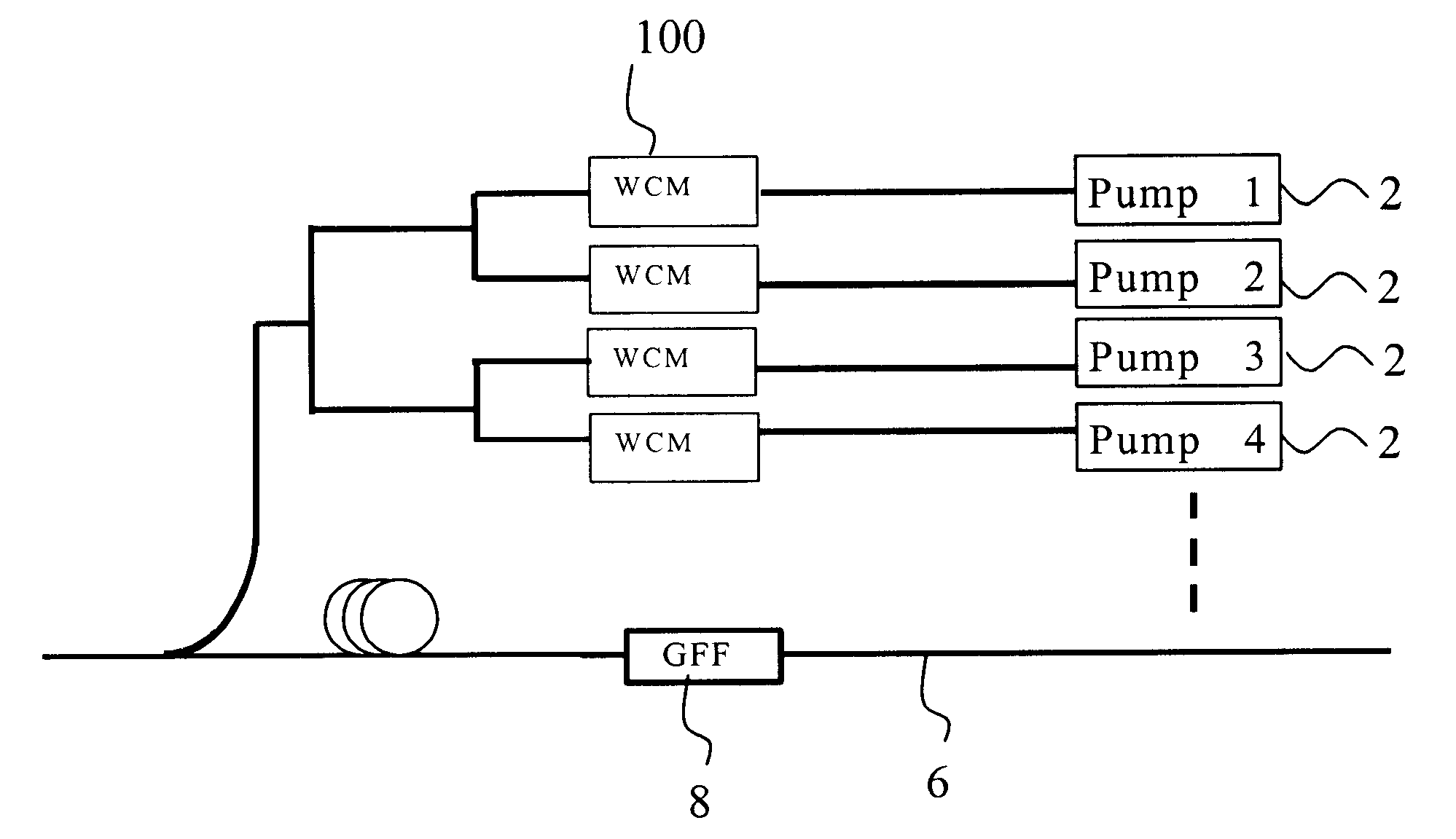
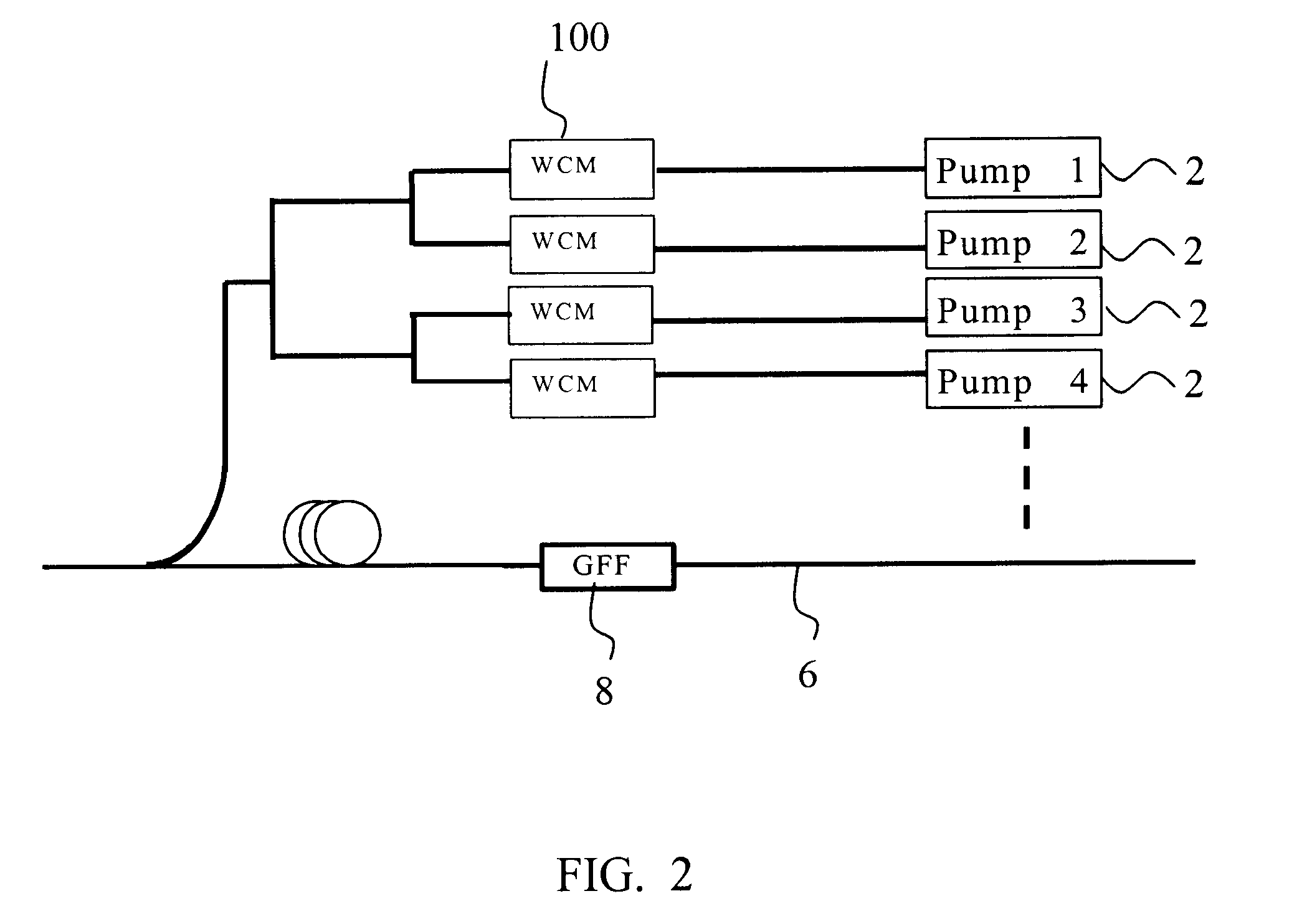
FIG. 2 is a block diagram of a portion of an optical communications system in an embodiment of the invention. The system includes a Raman amplifier which includes a number of pump la...


PUM


Abstract

An exemplary embodiment of the invention is a Raman amplifier for use in an optical communications network. The Raman amplifier includes a plurality of pump lasers and a plurality of wavelength control modules, each associated with one of the pump lasers. Each wavelength control module includes a fiber Bragg grating optically coupled to a respective one of the plurality of pump lasers. The fiber Bragg grating receives a pump laser output from one of the pump lasers and generates a wavelength control module output. A temperature sensor is in thermal contact with the fiber Bragg grating and generates a temperature signal indicative of a temperature of the fiber Bragg grating. A controller is operatively connected to the temperature sensor and generates a control signal in response to the temperature signal. A thermal regulator is in thermal contact with the fiber Bragg grating and adjusts the temperature of the fiber Bragg grating in response to the control signal. The controller adjusts the temperature of the fiber Bragg grating to reduce sensitivity of Raman gain flatness to variation in a wavelength of the pump laser output.

Description

1. Field of InventionThe invention relates generally to a method and system for controlling Raman gain flatness sensitivity to pump laser wavelength variations in an optical communications system utilizing Raman amplification.2. Description of Related ArtRaman amplifiers are used in optical communications networks in applications such as ultra long haul transmissions. Energy from pump lasers is transferred to the signal carrying wavelengths through stimulated Raman scattering (SRS) to thereby amplify the signal.In wavelength division multiplexed (WDM) systems, it is known to be desirable to provide uniform gain across multiple channels, a concept referred to as gain flatness. Unfortunately, conventional Raman amplifiers may generate non-uniform gain due to a number of factors. First, the pump lasers will have variance in the output wavelength due to manufacturing tolerances. Typically, pump laser manufacturers can deliver pump lasers with .+-.1.0 nm tolerance at room temperature (25...

Claims


Application Information

Patent Timeline
Patent Type & Authority Patents(United States)
IPC IPC(8): H01S3/30H01S3/131H01S3/094H01S5/14H01S5/00H01S5/06
CPCH01S3/302H01S3/094003H01S3/094096H01S3/1312H01S2301/04H01S5/0612H01S5/146
Inventor CHO, SI HYUNGTSOU, JONBAO, JUNSRIDHAR, BALAKRISHNAN
Owner CIENA
Why Eureka
Try Eureka