Devices for controlling the position of an underwater cable

a technology for controlling the position of underwater cables, applied in underwater equipment, special-purpose vessels, instruments, etc., can solve the problems of water entering the interior of the cables, batteries have a number of serious drawbacks, batteries have a limited life span, and must be replaced

Inactive Publication Date: 2003-02-25
INPUT OUTPUT INC
View PDF27 Cites 188 Cited by
  • Summary
  • Abstract
  • Description
  • Claims
  • Application Information

AI Technical Summary

Problems solved by technology

It is possible to connect such external devices with a source of power aboard the towing vessel by means of wires passing through the skin of the cable, but the necessity of forming holes in the skin for the wires can lead to leakage of water into the interior of the cable, which is highly undesirable.
However, batteries have a number of serious drawbacks.
First, the batteries have a limited life span and must be replaced every one to three months.
Not only is the replacement of the batteries time-consuming, there is also the risk of exposing electric circuitry within the external device to sea water during replacement.
In addition, lithium primary batteries, which are used because of their longer operating life compared to other batteries, are expensive, and spent batteries must be retained for proper disposal and not randomly discarded.
Furthermore, each time the cable is reeled in to replace batteries in the external devices, it is subjected to stresses which frequently result in damage to the cable.
In rough seas, it can be extremely difficult and often dangerous for workers to remove the external devices from or reattach them to the cable on the deck of the towing vessel.
Furthermore, onboard storage space, often a precious commodity, must be provided for the external devices on board the towing vessel.
In addition, the reeling in or paying out of the underwater cable must be stopped during removal or reattachment of the external devices, so deployment and retrieval of the cable are time consuming.
Therefore, the load on any batteries in the external device is small, and the batteries can be used for long periods within requiring replacement.

Method used


Image

  • Devices for controlling the position of an underwater cable
  • Devices for controlling the position of an underwater cable
  • Devices for controlling the position of an underwater cable

Examples


Embodiment Construction

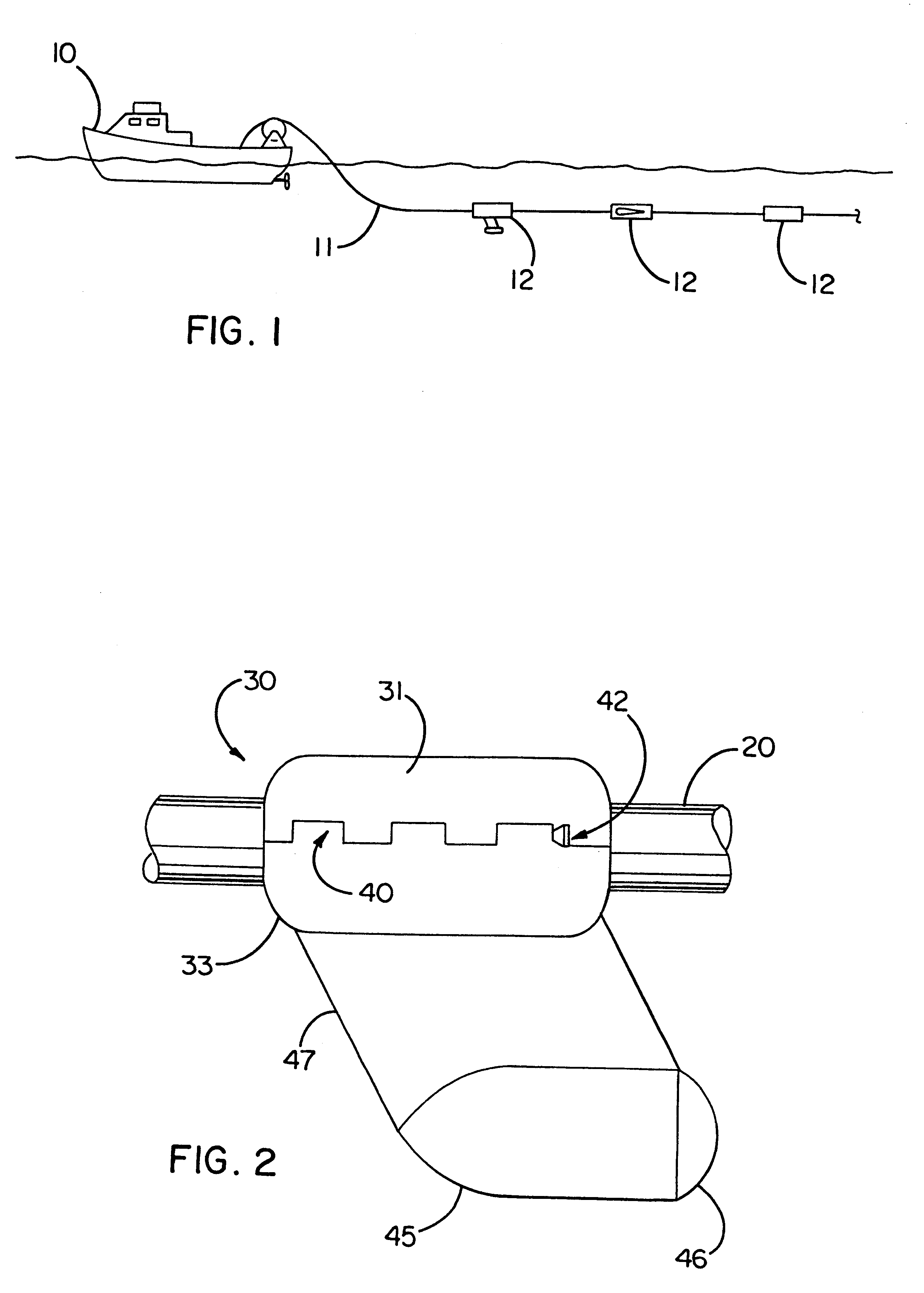
FIG. 1 schematically illustrates an example of an underwater cable arrangement according to the present invention. The arrangement includes an underwater cable 11 being towed through the water by a towing vessel 10, such as an ordinary surface vessel, although the cable 11 can also be towed by an underwater vessel or by an aircraft. One or more external devices 12 are attached to the underwater cable 11 at intervals along its length. For simplicity, only three external devices 12 are illustrated, but there is no restriction on the number or type of devices which are attached to the cable 11. In addition, although only a single cable 11 is shown, the towing vessel 10 may tow a plurality of cables simultaneously.

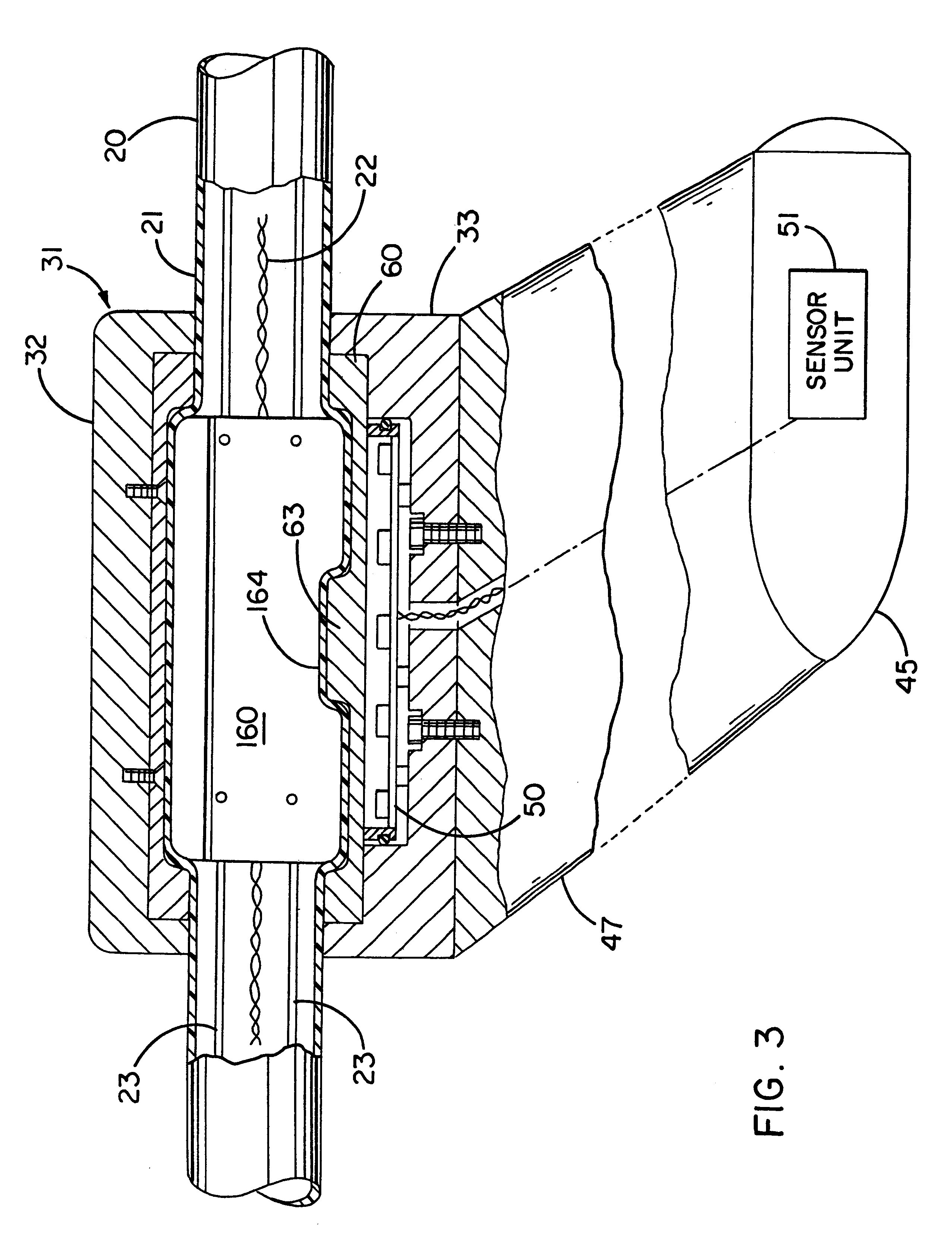
FIGS. 2 through 6 illustrate a first embodiment of an external device 30 which can be mounted on an underwater cable 20. FIGS. 2 and 3 show the external device 30 as it would appear when being towed through the water by the cable 20 to the left in the figures. The external dev...


PUM


Abstract

A device for controlling the position of an underwater cable comprises a body, first and second actuators, and a pair of wings. The body is stationarily mountable to the underwater cable and the first and second actuators are disposed in the body. Each wing has an axis of rotation and the wings are coupled to the first and second actuators to control the depth and the horizontal position of the underwater cable in the water.

Description

1. Field of the InventionThis invention relates to an underwater cable arrangement capable of being used, for example, in seismic testing.2. Description of the Related ArtIn marine seismic exploration, an underwater cable, commonly referred to as a streamer cable, is towed through the water by a vessel such as a surface ship. An array of hydrophones is mounted within the cable, and an acoustic source or gun is fired to force an impulse of compressed air into the water, creating a bubble. The collapse of the bubble generates acoustic pulses that radiate through the water and into the earth. Reflections of the pulses off geologic structures are picked up by the hydrophones, and data representing the detected reflections are transmitted to the towing vessel. By analyzing the reflections, it is possible to discover subsea formations of oil or gas.Various devices requiring electric power for their operation are mounted on the exterior of the underwater cable. For example, in order to acc...

Claims


Application Information

Patent Timeline
Patent Type & Authority Patents(United States)
IPC IPC(8): G01V1/16G01V1/20G01V1/38G01V1/22H04B3/44H04B3/02H04B3/36
CPCG01V1/201G01V1/22H04B3/44H04B3/36G01V1/3826
Inventor OLIVIER, ANDRE W.ROUQUETTE, ROBERT E.RAU, BRIEN G.
Owner INPUT OUTPUT INC
Why Eureka
Try Eureka