Structure of a ball grid array IC socket connection with solder ball

a grid array and ic socket technology, applied in the direction of fixed connections, coupling device connections, electrical apparatus construction details, etc., can solve the problems of reducing the conductivity at the soldering point, troublesome repeating of soldering processes, and affecting the quality of the soldering poin

Inactive Publication Date: 2003-03-11
LOTES
View PDF7 Cites 33 Cited by
  • Summary
  • Abstract
  • Description
  • Claims
  • Application Information

AI Technical Summary

Benefits of technology

Accordingly, it is an object of the present invention to provide an improved structure of a Ball Grid Array IC socket connection with solder ball, wherein the conductive plate is formed from bendable, flexible conductive thin plate surrounded to form slotted cylindrical tube for the insertion and clipping of IC pins. The slotted cylindrical tube can be in the form of square shape, and in particular the tube opening at the other end of the slotted tube for the insertion of the IC pins, wherein the size of the tube diameter can tightly clip the ball wall of a solder ball, such that the tube opening mounted with the solder ball provides a tight connection. On the other end of the slotted cylindrical tube, remote from the end inserted with IC pins, at a position about half the height of the solder ball, an arc-shaped slit is provided so that a blocking plate is joined to the wall of the tube, and the blocking plate touches the top portion of the solder ball.
Yet another object of the present invention is to provide an improved structure of a Ball Grid Array IC socket connection with solder ball, wherein the IC socket is provided with a plurality of conductive clipping plates to connect with the solder ball, the surrounding of the inner wall of the wall block is a through slot allowing the mounting of the slotted cylindrical tube.

Problems solved by technology

(1) A soldering process is required to pre-mount the solder ball onto a conductive clipping plate and after that when the CPU socket is be adhered to the circuit board, the solder ball has to be heated again, and accordingly, repeating of soldering processes is troublesome and the fabrication processes cannot be expedite; and
(2) Due to numerous soldering points, chances of pollution due to air pollutant are increased and therefore the quality of conductivity at the soldered point is lowered, and further, the connection structure of the solder ball is inappropriate.

Method used


Image

  • Structure of a ball grid array IC socket connection with solder ball
  • Structure of a ball grid array IC socket connection with solder ball
  • Structure of a ball grid array IC socket connection with solder ball

Examples


Embodiment Construction

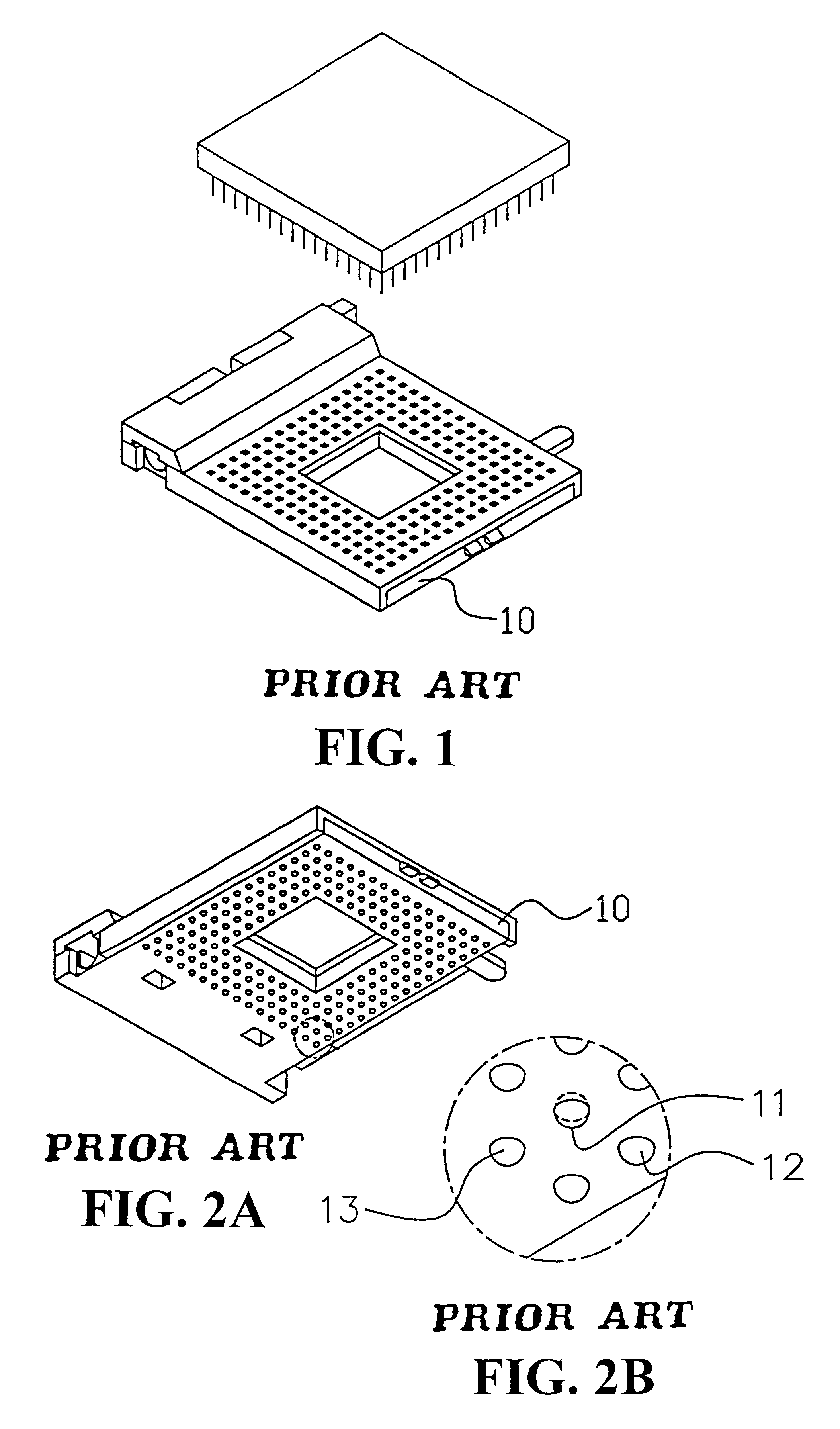
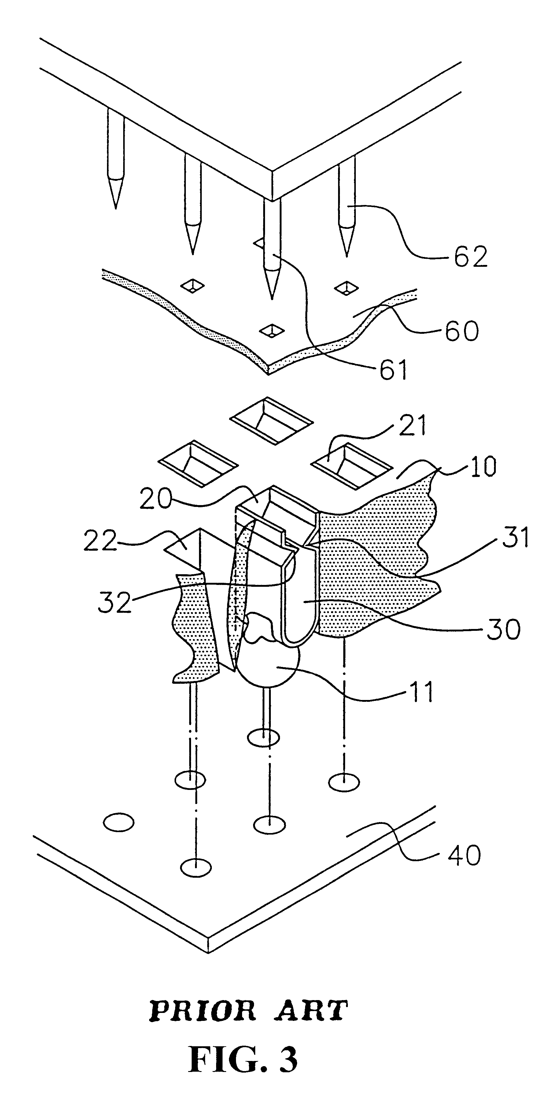
FIGS. 1 and 2A respectively show a perspective view and the bottom perspective view of a Ball Grid Array IC socket, and FIG. 3 is a perspective view of a conventional Ball Grid Array CPU socket connected with solder ball structure.

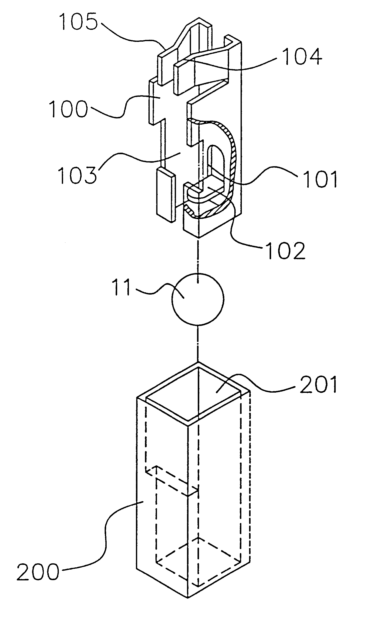
Referring to FIGS. 4 and 5, there is shown a perspective view and a perspective exploded view of the connection of the conductive clipping plate of the solder ball with the Ball Grid Array IC socket in accordance with the present invention. As shown in the figures, within the IC socket, the conductive plate is formed from bendable, flexible conductive thin plate surrounded to form slotted cylindrical tube 100 for the insertion and clipping of IC pins. The slotted cylindrical tube 100 can be in the form of square shape, and in particular, the tube opening at the other end of the slotted tube 100 for the insertion of the IC pins is a square shape, wherein the size of the tube diameter can tighdy clip the ball wall of a solder ball 11, such that the tube open...


PUM


Abstract

A Ball Grid Array IC Socket connection with solder ball is characterized in that the conductive plate is formed from bendable, flexible conductive thin plate surrounded to form slotted cylindrical tube for the insertion and clipping of IC pins. The slotted cylindrical tube is in the form of square shape, wherein the size of the tube diameter can tightly clip the ball wall of a solder ball, such that the tube opening mounted with the solder ball provides a tight connection. On the other end of the slotted cylindrical tube, remote from the end inserted with IC pins, at a position about half the height of the solder ball, an arc-shaped slit is provided so that a blocking plate is joined to the wall of the tube, and the blocking plate touches the top portion of the solder ball.

Description

(a) Field of the InventionThe present invention relates to an improved structure of a Ball Grid Array IC socket connection with solder ball, and in particular, an IC socket having a plurality of conductive clipping plates with clipping solder ball structure so as to eliminate the requirement of pre-soldering of solder ball onto the conductive clipping plates.(b) Description of the Prior ArtBall Grid Array IC socket is a new IC (integrated circuit) socket structure with solder balls to replace the insertion pins protruded from the bottom of the socket, and surface mounting technology is employed to mount the corresponding soldering position of the solder balls over the surface of the circuit board. FIG. 1 is a perspective view of Ball Grid Array CPU (central processing unit) socket. FIG. 2A is a bottom view of the socket shown in FIG. 1 and FIG. 2B is an enlarged view of a portion of FIG. 2A. The number of mounting pins of the corresponding IC pins of the socket is changed to a socke...

Claims


Application Information

Patent Timeline
Patent Type & Authority Patents(United States)
IPC IPC(8): H05K7/10H01R12/57
CPCH05K7/1069H01R12/57
Inventor JU, TED
Owner LOTES
Why Eureka
Try Eureka