
Biological fluidized bed apparatus

Inactive Publication Date: 2003-03-11
INT WASTE MANAGEMENT SYST
View PDF8 Cites 31 Cited by
  • Summary
  • Abstract
  • Description
  • Claims
  • Application Information

AI Technical Summary

Benefits of technology

This biological fluidized bed apparatus provides a pre-fabricated, modular, self-contained biological reactor, which can treat municipal, industrial and confined animal feedlot wastewater at high loading rates. This reactor design overcomes the limitations and disadvantages of prior fluidized bed reactor configurations by means of its shape and internal components. As a result, it provides better quality effluent, requires less "foot print" area for installation and demands less maintenance.
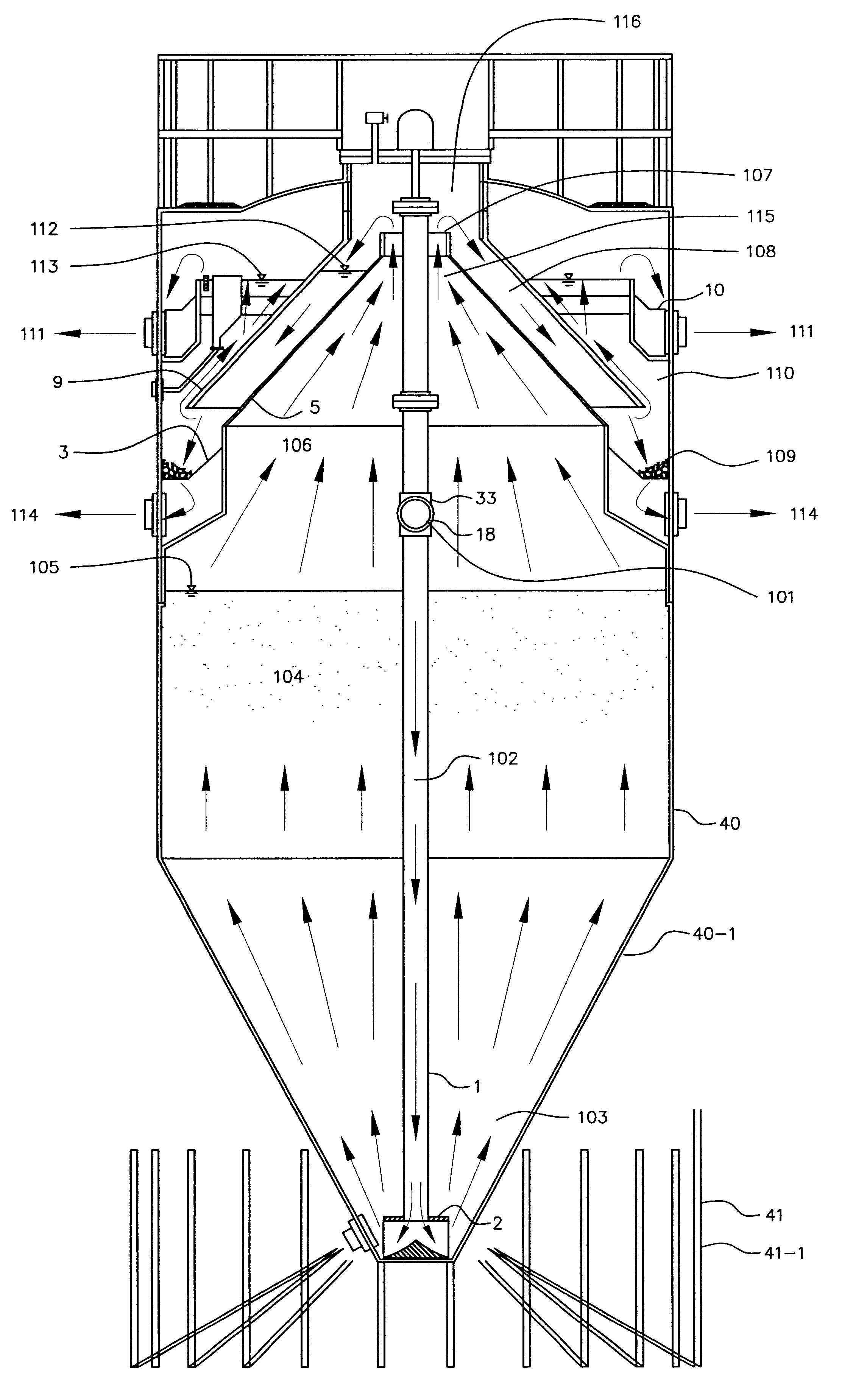
A. Uniform flow distribution at the bottom of the bed. This is achieved using a reactor tank with a 60-degree conical bottom (inverted truncated cone) and a single internal down-coming pipe discharging recirculated flow at the bottom of the cone. In order to limit turbulence at the bottom of the reactor, the flow exits the pipe radially by means of a molded flow distribution fitting. This fitting, which changes the direction of the flow from vertical to radial, is contoured internally to reduce losses and smoothen the change of direction of the flow lines. The open area of the flow distribution fitting is such that exit velocities are sufficiently high to drag the larger bioparticles located at the bottom of the reactor. The required drag velocity is achieved at a flow sufficient to create the upflow velocity required for the minimum admissible bed expansion. The proposed flow distribution design eliminates nozzle clogging, since a single fitting is used instead of a network of multiple small diameter nozzles. With this design, no channeling or "dead zones" form in the bed. Additionally, bed expansion is uniform and can be controlled very precisely by adjusting the recirculation flow. A more uniform fluidization enables gas bubbles to be released evenly throughout the section of the bed.
B. Media with a lower particle size uniformity coefficient can be efficiently fluidized. The conical bottom reactor design allows a wider range of particle sizes in the media to be fluidized, as a result of the various upflow velocities occurring through the conical portion of the reactor. At a constant recirculation flow, upflow velocities gradually decrease from the bottom of the inverted cone through the cylindrical portion of the tank. This is a result of the change in sectional area of the conical portion. Having various upflow velocities in the lower section of the reactor accommodates the use of a wider range of particle sizes in the media. Larger, heavier particles will concentrate towards the bottom of the cone, where higher upflow velocities occur due to reduced cross-sectional area. Accordingly, smaller, lighter particles will accumulate in the upper section of the cone, which has lower upflow velocities. This feature enables the use of biofilm support media with less uniform particle size. This reduces the cost of the media since it can be purchased as a readily available commercial product.
Gas bubbles are isolated from the clarification zone and do not interfere with this process. The clarification zone has a gradual increase in cross-sectional area; thus, it operates as an upflow solids contact clarifier. On top of the clarification zone, an effluent trough disposed on the perimeter of the reactor collects the effluent overflow. An effluent launderer, installed along the trough, retains floating solids. A slow-rotating skimmer arm connected to the same sweeping mechanism of the submerged trough, pushes scum and floating solids on the surface of the water into a scum box. Scum and floatables collected in this box are removed by means of an electrically actuated valve. This internal solids / gas / liquid separator provides a reliable means for separation of the three phases. The separator provides an enclosed volume above the surface of the water for the accumulation and removal of biogas.

Problems solved by technology

Despite the great advantages that this process offers in terms of high organic loading rates, short hydraulic retention times and low excess solids generation, the use of these reactors has not been extensive due to various design limitations.
(a) Inadequate Flow Distribution at the Bottom of the Bed
In current fluidized bed reactor configurations, clogging of distribution nozzles and the existence of "dead zones," channeling and short-circuiting inside the bed are major disadvantages.
Such bed disruptions deteriorate the quality of the effluent by releasing solids trapped within the bed.
Although the solution to inadequate bed expansion would appear to be increasing the recirculation flow in order to achieve higher upflow velocity, this presents the disadvantage of washing solids trapped in the bed, by the high interstitial velocities created by the increased flow.
These solids deteriorate the quality of the effluent.
Commercially available media are not highly uniform in particle size.
A more uniform particle size media has a higher cost, since narrow particle size range sieving produces more wasted material in the for the media manufacturer.
On the other hand, at an upflow velocity, at which small media particles reach adequate fluidization, large particles remain unexpanded at the bottom of the reactor, creating a plug and hindering uniform expansion.
(d) Difficulty in Removing Excess Solids from the Reactor
Anaerobic bacteria are slow growers, however as a result of substrate consumption there is biomass growth.
However, failure to accumulate and remove excess biomass without disturbing the operation of the reactor, will affect the performance of the unit and the quality of the effluent.

Method used


Image

  • Biological fluidized bed apparatus
  • Biological fluidized bed apparatus
  • Biological fluidized bed apparatus

Examples


Embodiment Construction

. 1-9)

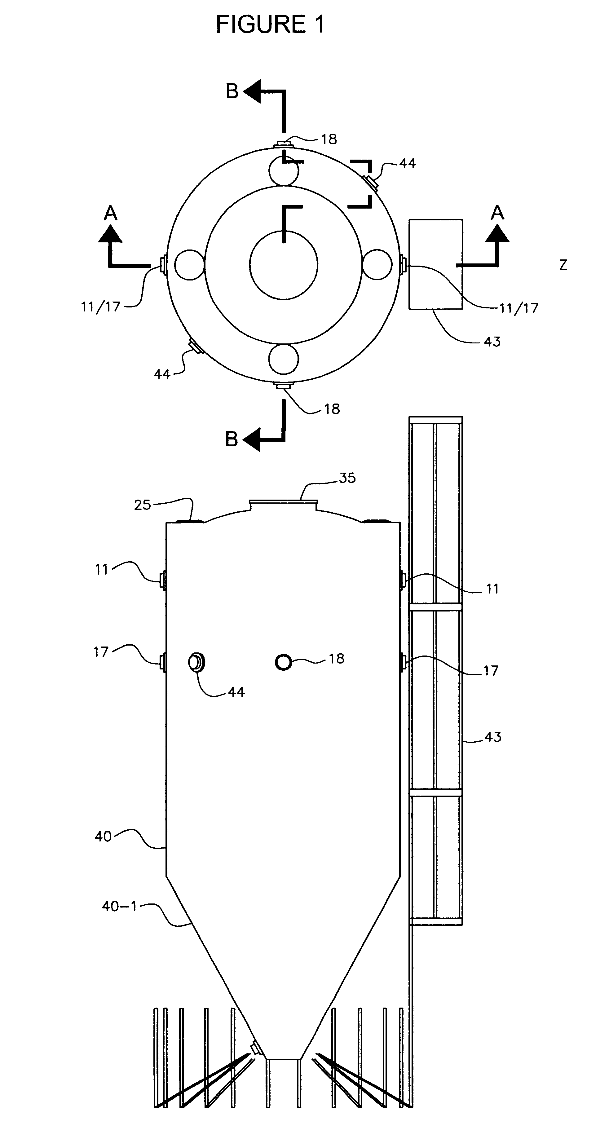
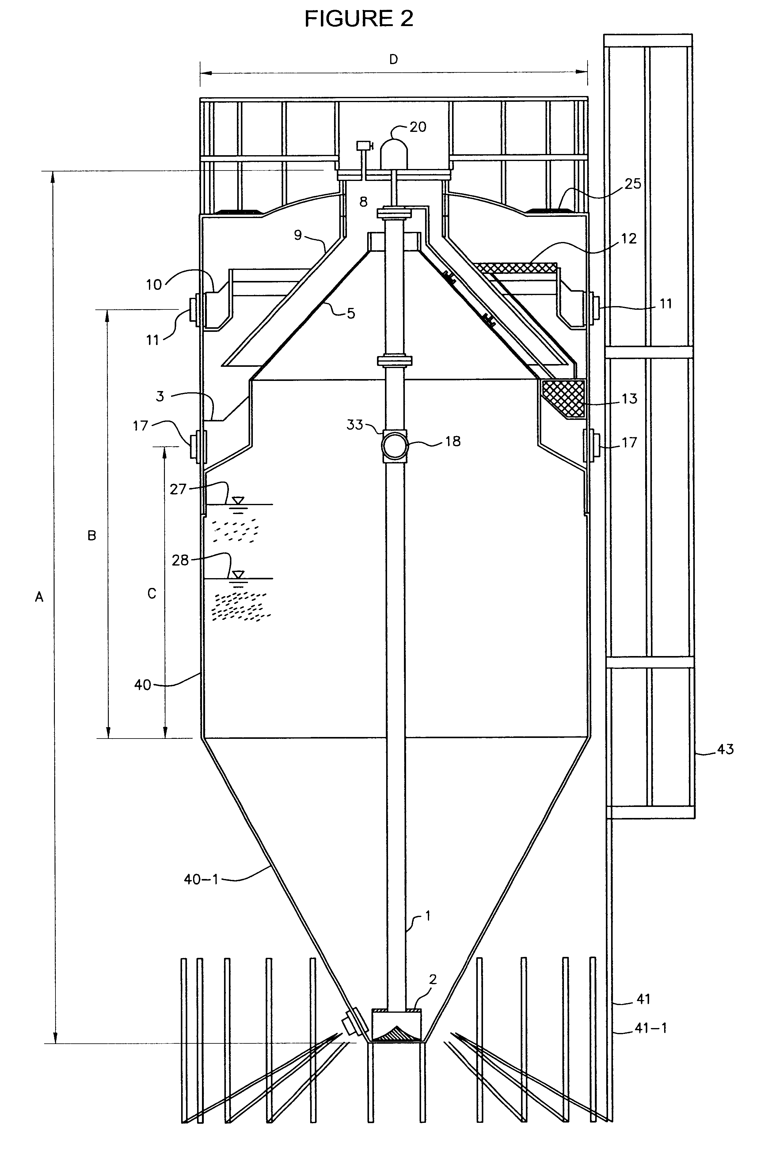
The biological fluidized bed apparatus depicted in the figures is a modular, prefabricated reactor. The dimensions shown in FIG. 2 correspond to the largest unit, for example, that can be pre-fabricated and transported from the manufacturing facility to the project site. The dimensions in FIG. 2 and other figures are for reference only. Reactors of any size can be manufactured maintaining proportional dimensions as shown in the figures.

Projects that require larger treatment volume should use two or more units connected in parallel or in series, depending on the application.

A typical embodiment of the biological fluidized bed apparatus is illustrated in FIG. 2. This drawing shows part of the reactor base, access ladder and safety railing at the top of the unit. Although the reactor design presented in the drawings was developed for low-density linear polyethylene, it can be fabricated in carbon steel plate, stainless steel or fiberglass, or other suitable materials.

Since the pr...


PUM

PropertyMeasurementUnit
Angleaaaaaaaaaa

Abstract

A pre-fabricated, self-contained biological fluidized bed apparatus for the treatment of wastewater, which offers easy and uniform expansion for various types of commercially available media, by means of a conical bottom and a single, non-clogging flow distribution pipe. Besides the biological treatment accomplished within the fluidized bed, this reactor provides mechanical solids / gas / liquid separation and upflow sludge blanket clarification to improve effluent quality. Additional unique features of this apparatus are a rotating surface skimmer and an excess sludge collection and thickening device powered by an externally mounted drive. With this reactor configuration, anaerobic and anoxic biological treatment and subsequent clarification are achieved in a single enclosed tank.

Description

1. BACKGROUND OF THE INVENTION1.1 Field of the InventionThe invention pertains to a specific design of a biological fluidized bed apparatus to treat wastewater. The invention claimed here is the particular design of the apparatus and its components.1.2 Description of the Prior ArtOver the last twenty years, extensive research has been done in the US, Europe and Japan to develop various fluidized bed reactor configurations and processes. Important patented contributions in this field have been made by the following:Rovel et al. (pat: U.S. Pat. No. 4,482,458)Vogelpohl et al. (pat: U.S. Pat. No. 4,940,546)Edwards (pat: U.S. Pat. No. 5,441,634)Yoda et al. (pat: U.S. Pat. No. 4,762,612)Clark et al. (pat: U.S. Pat. No. 5,942,116)Love (pat: U.S. Pat. No. 4,530,762)Klein (pat: U.S. Pat. No. 5,573,671)Biological fluidized bed reactors have been widely used to remove dissolved and suspended organic matter from high-strength industrial effluents. In this application, the biological beds are co...

Claims


Application Information

Patent Timeline
IPC IPC(8): C02F3/12
CPCC02F3/2833
Inventor JOSSE, JUAN CARLOSSUTHERLIN, JOHN WILLIAM
Owner INT WASTE MANAGEMENT SYST
Learn More