Safety method, device and system for an energy storage device

a technology of energy storage device and safety method, applied in safety/protection circuit, primary cell maintenance/service, batteries, etc., can solve the problems of limiting charging and discharging, disconnecting batteries, and failing to mitigate overheating

Inactive Publication Date: 2003-03-11
QUALLION
View PDF11 Cites 94 Cited by
  • Summary
  • Abstract
  • Description
  • Claims
  • Application Information

AI Technical Summary

Problems solved by technology

The circuits typically limit charging and discharging, or disconnect a battery in the event of over-heating or over-pressure in the battery.
Each of the foregoing approaches fails to mitigate over-heating caused by a short circuit internal to a battery (as opposed to battery heating caused by an external short).
A short circuit resulting from faulty manufacture, however, such as a contaminant lodged in the components of a battery during assembly creating a hole in the separator, growth of dendrites within the battery or crushing or penetration of the battery can defeat the safety features of the safety separator, causing a runaway condition and overheating.
The large flow of current through such an internal short can cause heat and pressure to rise dramatically inside the battery.
Each of the foregoing prior art approaches (both the use of safety circuits and safety separators) further suffers from the problem that the energy stored in the battery may continue to over-heat the battery, causing a build-up in pressure, explosion or combustion resulting in rupture of the battery enclosure, and / or leaks of electrolyte.
However, such an arrangement is impractical for small batteries, especially those that are medically implanted.
Moreover, such a thermal sink would likely not dissipate heat quickly enough in the event of an internal short circuit, especially one caused by a sudden penetration or crushing event.
Thus, a passive heat sink such as described in the '667 patent would likely not prevent a runaway condition and may not be adequate to prevent electrolyte leaks, explosions or even combustion.
If such conditions persist, even if the external load is disconnected, electrolyte leakage, explosion and combustion can occur.

Method used


Image

  • Safety method, device and system for an energy storage device
  • Safety method, device and system for an energy storage device
  • Safety method, device and system for an energy storage device

Examples


Embodiment Construction

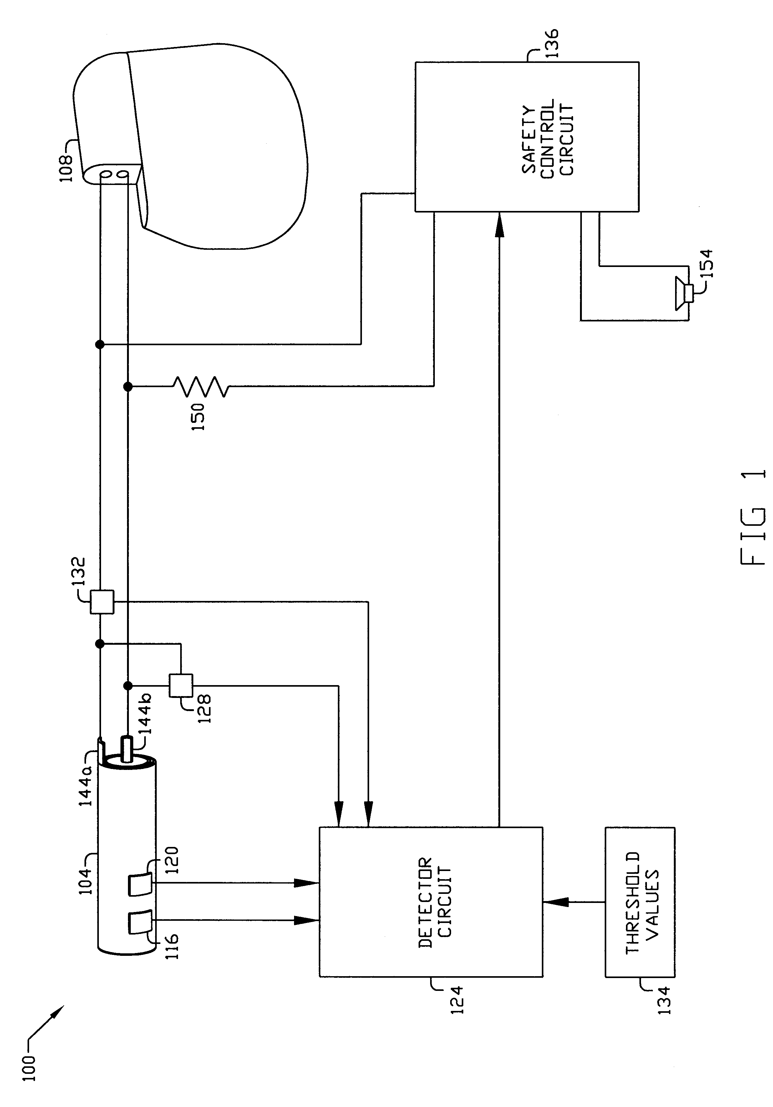
Referring to the drawings, FIG. 1 is a schematic diagram illustrating the best mode of the claimed safety circuit 100 having a battery 104 powering an external device 108 (such as a spinal cord stimulator ). Sensors 116 and 120 detect temperature and pressure respectively, and are connected to a detector circuit 124 which also measures voltage 128 across and current 132 traveling through the battery 104. Predetermined threshold values 134 are stored in the memory of the detector circuit 124 and, in the event of an internal fault in the battery (e.g., over-heating of excessive pressure in, or high current flow through the battery), the detector circuit 124 signals the safety control circuit 136 to initiate an emergency energy discharge sequence including connection of the terminals 144a and 144b of the battery 104 to an energy discharge device 150. Simultaneously, the safety control circuit 136 initiates an alert signal device 154 to alert the operator or user that a failure has take...


PUM

PropertyMeasurementUnit
porosityaaaaaaaaaa
porosityaaaaaaaaaa
breaking timeaaaaaaaaaa

Abstract

A method, device and system is disclosed for rapidly and safely discharging remaining energy stored in an electrochemical battery 104 in the event of an internal short circuit or other fault. In its best mode of implementation, if a sensor 116 detects one or more parameters such as battery temperature 204 or pressure 206, exceeding a predetermined threshold value 334, the terminals 144 of the battery or cell are intentionally short-circuited external to the battery through a low or near zero resistance load 150 which rapidly drains energy from the battery 104. The rate energy is drained via the external discharge load 150 may be controlled with an electronic circuit 136 responsive to factors such as state of charge and battery temperature. Devices such as piezoelectric and Peltier devices 300, may also be used as emergency energy discharge loads.

Description

REFERENCE TO PRIOR-FILED APPLICATIONSNone.The invention relates generally to electrochemical storage cells (hereinafter referred to as "batteries"), and more particularly to safety circuits and systems to rapidly drain energy from a battery in the event of a fault or other malfunction.Batteries are now in use in a wide range of applications. This range of applications is expected to increase in the future as storage battery technology, particularly energy density, continues to improve. In recent years, implanted biomedical batteries have become important for powering so-called bionic devices such as cochlear implants, neuro-muscular stimulators, cardiac pacemakers and defibrillators and artificial organs. In addition, batteries have become an essential power source in a wide range of portable electronic devices including computers, personal information managers, radio telephones ("cellular telephones"), global positioning satellite (GPS) devices and other devices that combine the fu...

Claims


Application Information

Patent Timeline
Patent Type & Authority Patents(United States)
IPC IPC(8): H02J7/00H01M6/00H01M10/44H01M6/50H01M10/42
CPCH01M10/44H02J7/0029H01M10/446H01M2200/10H01M2200/20H01M2200/00Y02E60/10H02J7/00302H02J7/00308H02J7/00304H02J7/00309
Inventor TSUKAMOTO, HISASHIKISHIYAMA, CLAY
Owner QUALLION
Why Eureka
Try Eureka