
Method and apparatus for cleaning oil absorbent materials

a technology of absorbent materials and cleaning methods, applied in the directions of transportation and packaging, separation processes, filtration separation, etc., can solve the problems of not obtaining the cleanest materials and recycling of absorbed oil

Inactive Publication Date: 2003-03-25
MIDDLETON RICHARD G
View PDF12 Cites 6 Cited by
  • Summary
  • Abstract
  • Description
  • Claims
  • Application Information

AI Technical Summary

Benefits of technology

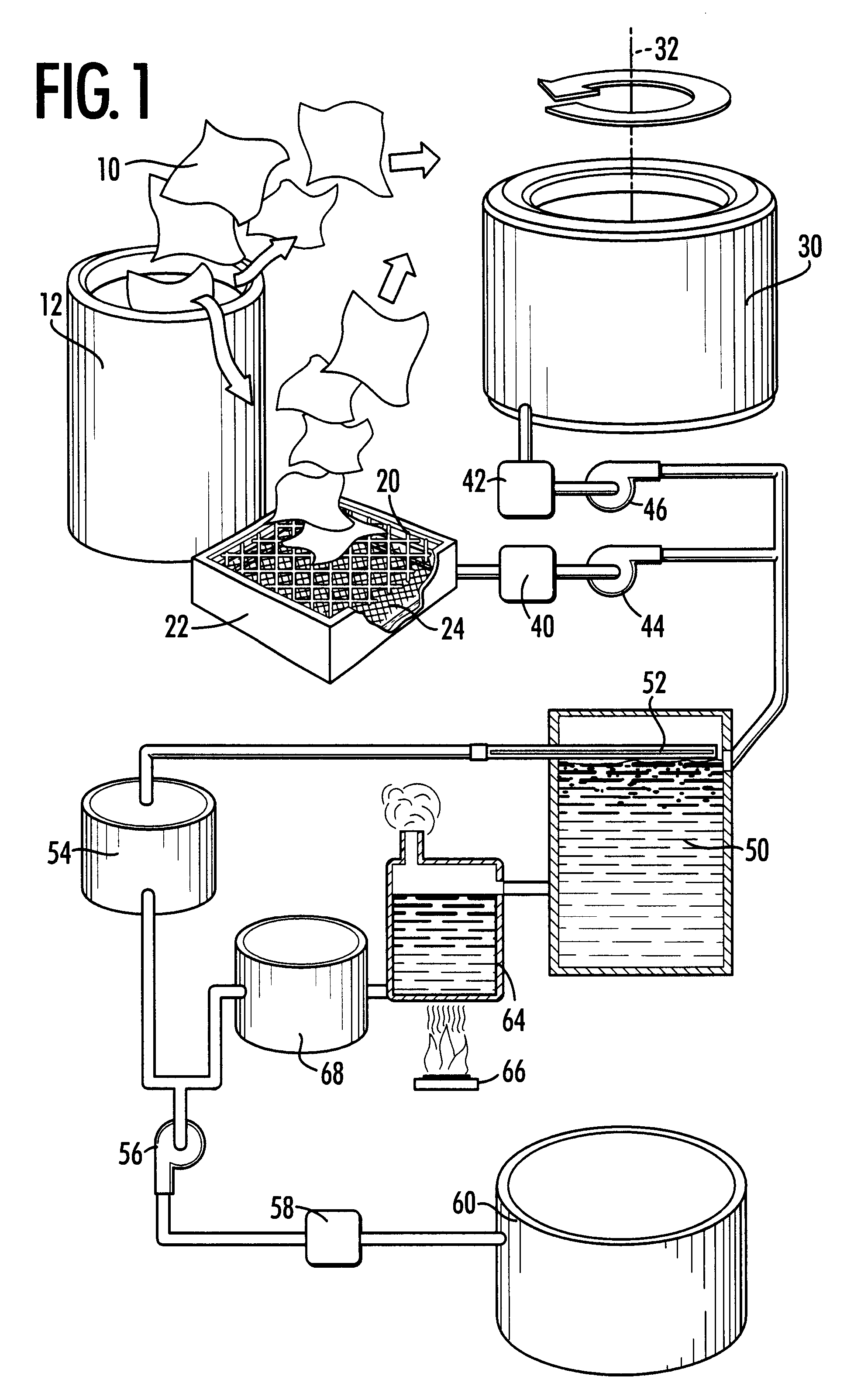
A feature of the present invention is the first component. A considerable amount of oil can be removed from oil-absorbent materials simply by allowing them to drain; however, even less oil will remain in these materials after centrifuging. By minimizing the amount of residual oil in the materials in the first component of the present process, more oil is recovered and the dry cleaning component is more effective in cleaning the materials for recycle. Furthermore, metal chips and particles can be removed by centrifusing before drycleaning the materials
Still another feature of the present invention is the use of gravity draining to remove excess oil before centrifuging. Not only does excess oil drain readily from the absorbing materials, but also particles and metal chips can be removed in this way. This step makes centrifuging and dry cleaning more efficient.
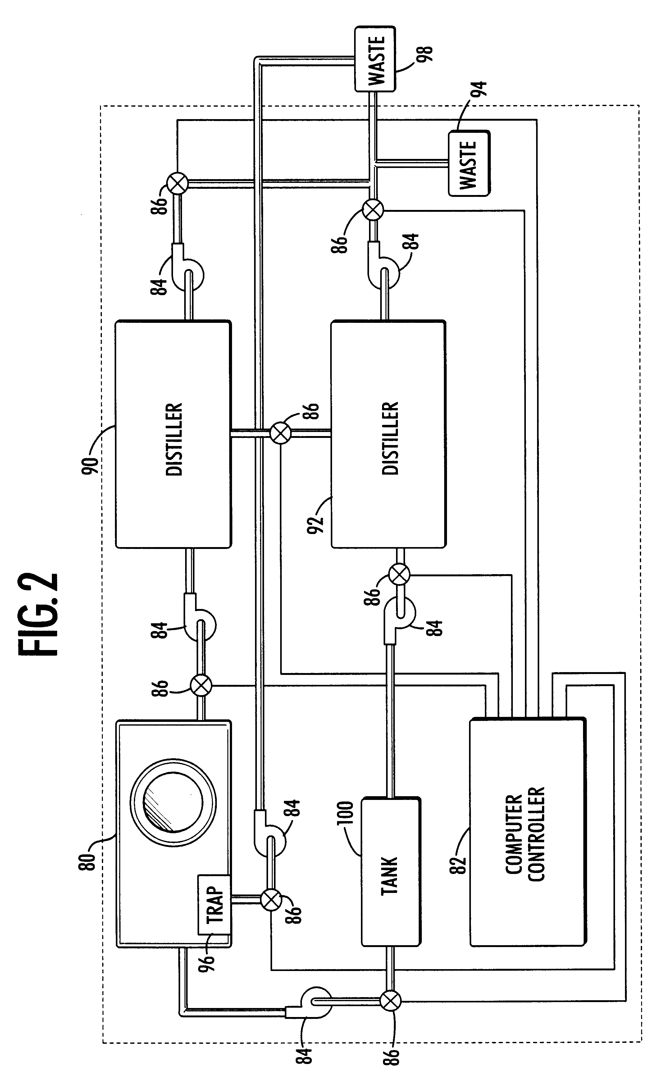
The use of an industrial distiller rather than a typical dry cleaning machine distiller is another important feature of the present invention. Because both the internal temperature and pressure can be precisely controlled, the independent distiller allows a more effective separation of the perchloroethylene from the lubricants. This in turn maximizes the purity of the recycled perchloroethylene and increases the recovery of lubricants.

Problems solved by technology

However, the goals of maximum recycle of absorbed oil and cleanest materials are not obtained necessarily by the same processes.
However, when the goal of the process is both to recycle absorbed oil and recycle clean oil-absorbing materials, as well as minimize the waste from the dry cleaning machine and limit damage from metal particles and chips, the combination of centrifuging and dry cleaning achieves these dual, conflicting goals.

Method used


Image

  • Method and apparatus for cleaning oil absorbent materials
  • Method and apparatus for cleaning oil absorbent materials
  • Method and apparatus for cleaning oil absorbent materials

Examples


Embodiment Construction

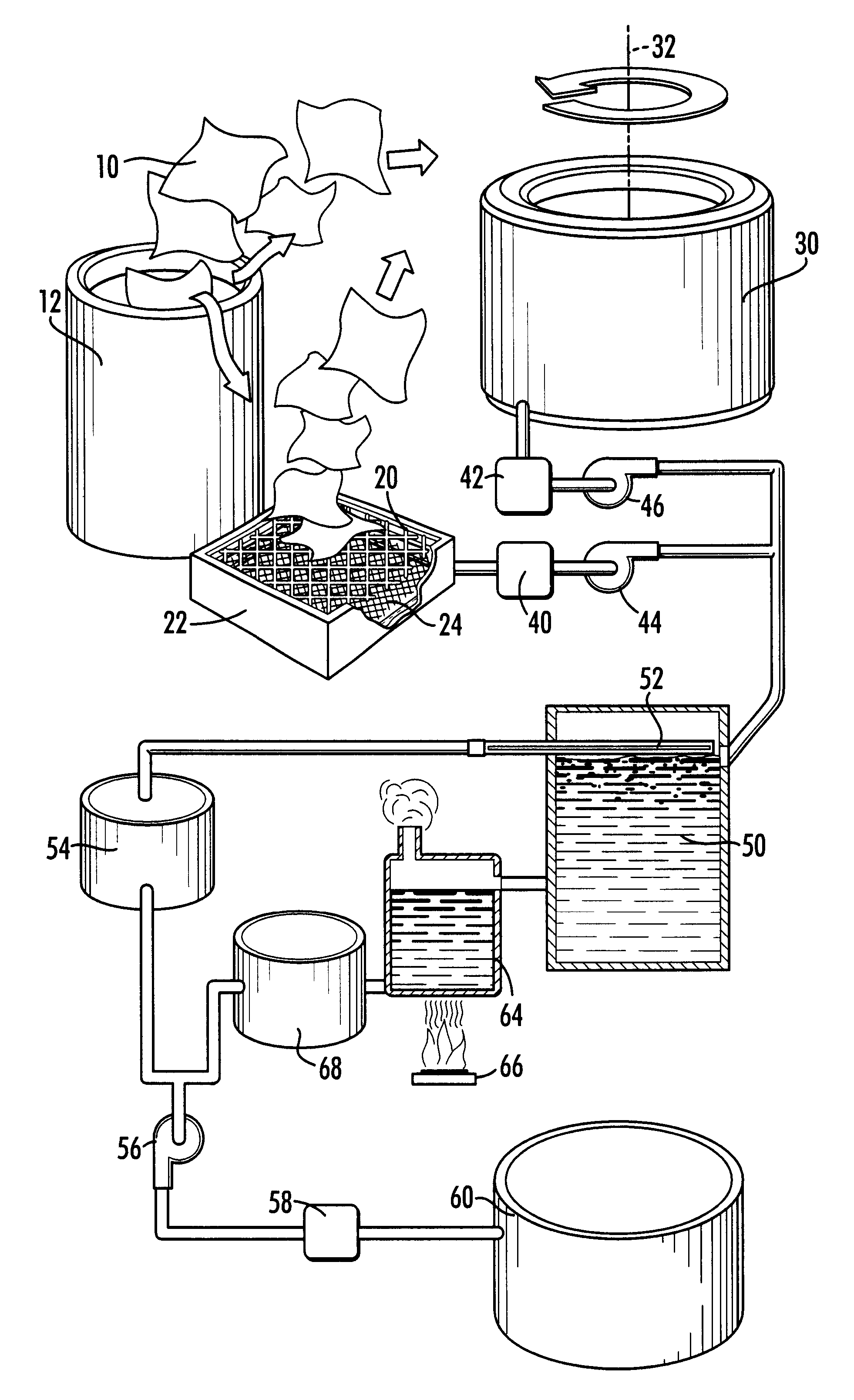
Referring now to FIGS. 1 and 2, there is shown a schematic diagram of a method and apparatus for separating oil from oil-absorbent materials according to a preferred embodiment of the present invention. Oil-absorbing materials include synthetic and natural, woven and non-woven pads and tubular "socks" that are customarily used in machine shops and metal fabricating plants to absorb spilled or leaking lubricants. These materials will be referred to herein and in the claims that follow as "pads" for convenience. Also, the present system is not intended for use with and will not work with solvents, only lubricants.

The goal of the present system is recycling; in particular, the present system recovers oil for recycling and cleans the oil-absorbing pads for reuse. The more effective the present system is, the more oil it recovers that can be recycled, the cleaner the oil-absorbing pads are and the less hazardous waste it generates. The first component of the present process is directed t...


PUM

PropertyMeasurementUnit
particle sizeaaaaaaaaaa
temperatureaaaaaaaaaa
compositionaaaaaaaaaa

Abstract

A method and system for separating oil form oil-absorbent materials for recycle of both the oil and the materials. The method comprises placing the oil absorbent material on a grid over a catch basin to drain, then centrifuging the material to remove additional excess oil. The excess oil is processed to separate water, grit, dirt, metal chips and shavings from it so that it can be sent to a refinery. After centrifuging to remove excess oils, the materials are dry cleaned in doubly distilled dry cleaning fluid to remove additional oil so that the materials can be reused.

Description

The present invention relates to a method and apparatus for separating oil from oil-absorbent materials so that both the materials and the oil can be recycled.DISCUSSION OF BACKGROUNDThe desorption of oil and other industrial lubricants from absorbent materials such as pads or "socks" is a prevalent industrial process. As a result, the current art contains a variety of different methods by which oil is either removed from an oil absorber or process after recovery for recycle of the oil or the materials are cleaned for reuse.The steps that are used to separate and recover oil from oil-absorbing materials for recycle must be chosen so that the desired results: maximum recycling and minimum waste generation are achieved. This type of optimization inevitably results in a process that is specific to a particular waste stream; that is, it will be dictated by the oil absorber and the composition of absorbed fluids and entrained solids.The steps that are used to clean the oil-absorbing mate...

Claims


Application Information

Patent Timeline
Patent Type & Authority Patents(United States)
IPC IPC(8): B01D41/00B01D41/02B09B3/00B08B7/00D06F43/08
CPCB01D41/02D06F43/081B09B3/0058B08B7/00B09B3/00B09B2101/02
Inventor MIDDLETON, RICHARD G
Owner MIDDLETON RICHARD G
Learn More