Method for controlling to cool a communication station

Inactive Publication Date: 2003-04-01
MITSUBISHI ELECTRIC CORP
View PDF20 Cites 36 Cited by
  • Summary
  • Abstract
  • Description
  • Claims
  • Application Information

AI Technical Summary

Problems solved by technology

However, some of casings have a space too narrow to receive a person.
However, in case that an air distribution in the casing is not preferable, there occur phenomenons that exhausted heat from the communication equipments resides and an air blown out of the indoor unit causes a short cycle.
Accordingly, the air conditioner does not deal with the real cooling load, whereby a temperature in the casing is increased or decreased; and environmental conditions of working temperature of the communication equipments are resultantly unsatisfied, and vapor is condensed in the air conditioner.
Further, because a density of components installed in the casing 103 is high in order to pursue compactness, it is impossible to provide a space for additional fans.
Therefore, there is a problem that a large-sized fan can. not be used, for example, a large airflow rate can not be supplied when the space of the casing 103 is unchanged.
When the electric power consumption is increased.
Repetition of the thermo-ons and the thermo-offs does not only shorten a lifetime of a compressor but also causes moisture condensation in the casing.
In such a case, it is insufficient to control using only the output signal

Method used


Image

  • Method for controlling to cool a communication station
  • Method for controlling to cool a communication station
  • Method for controlling to cool a communication station

Examples


embodiment 5

A structure according to Embodiment 5 of the present invention is illustrated in FIG. 24. The auxiliary cooling device, described in Embodiment 4, is substituted by a boiling type cooling device 31 including an evaporator 31a and a condenser 31b, wherein the evaporator 31a is located on an upper stream side in the airflow path, in which the main cooling device is located. The boiling type cooling device 31 has a characteristic that as a difference between an evaporative temperature in the evaporator 31a and a condensing temperature in the condenser 31b located in an outdoor unit of the boiling type cooling device increases, a capability is further demonstrated, basically in proportion thereto. Further, the boiling type cooling device 31 is inputted from only a blower 31c. Therefore, it is possible to highly efficiently use the air conditioner by making the air path of the indoor unit commonly use for that of the air conditioner and the air path of the indoor unit commonly use for th...

embodiment 6

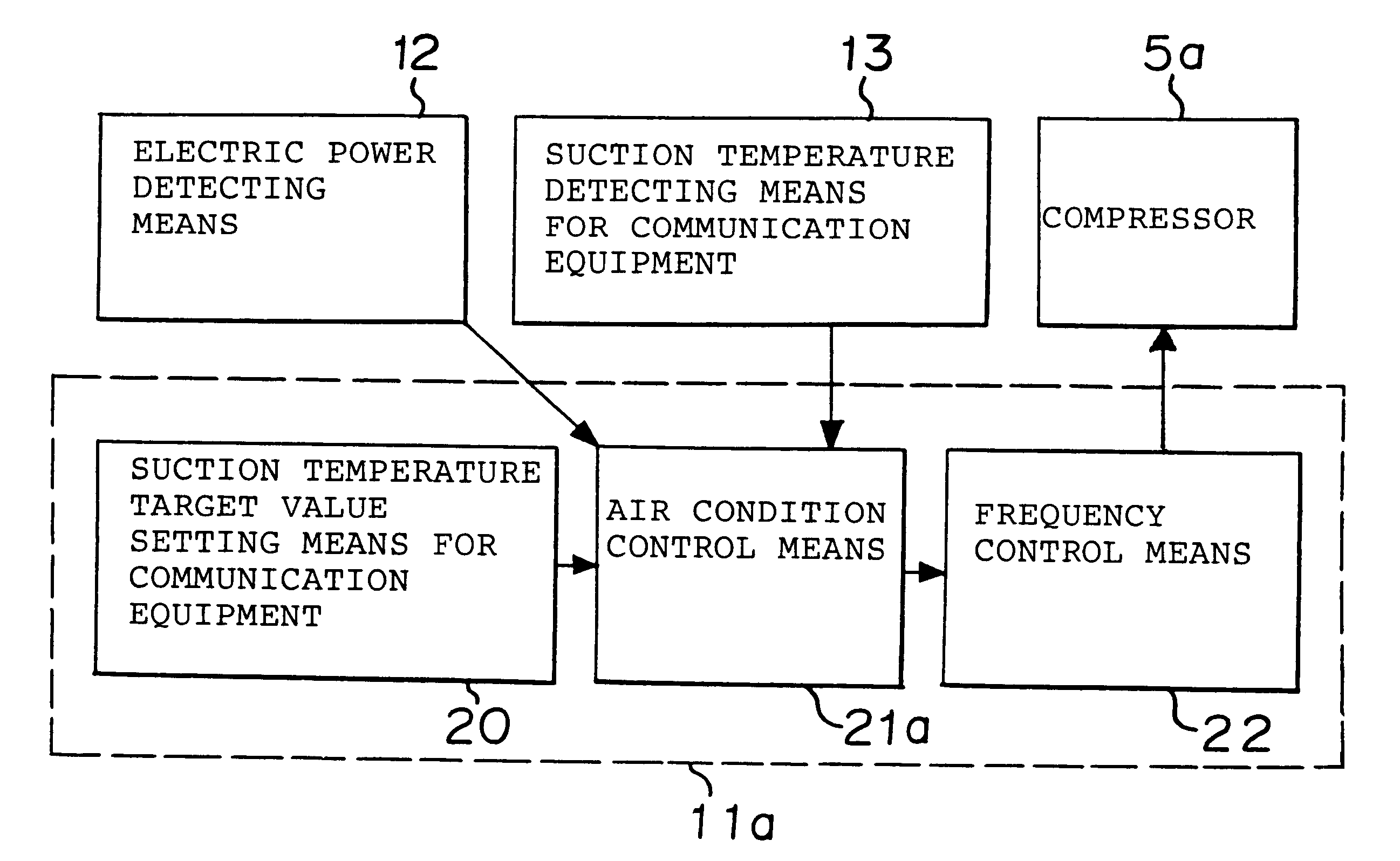
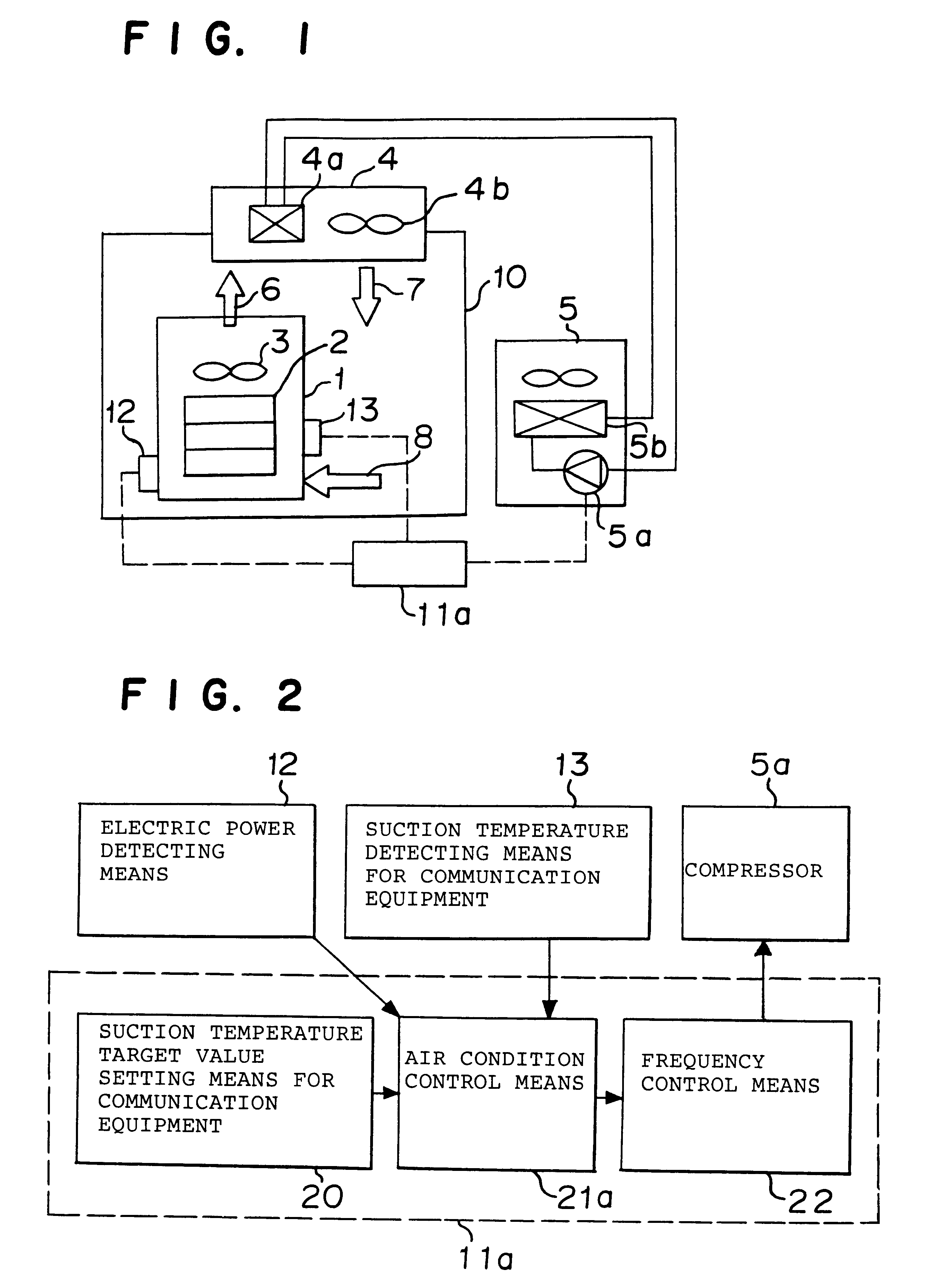
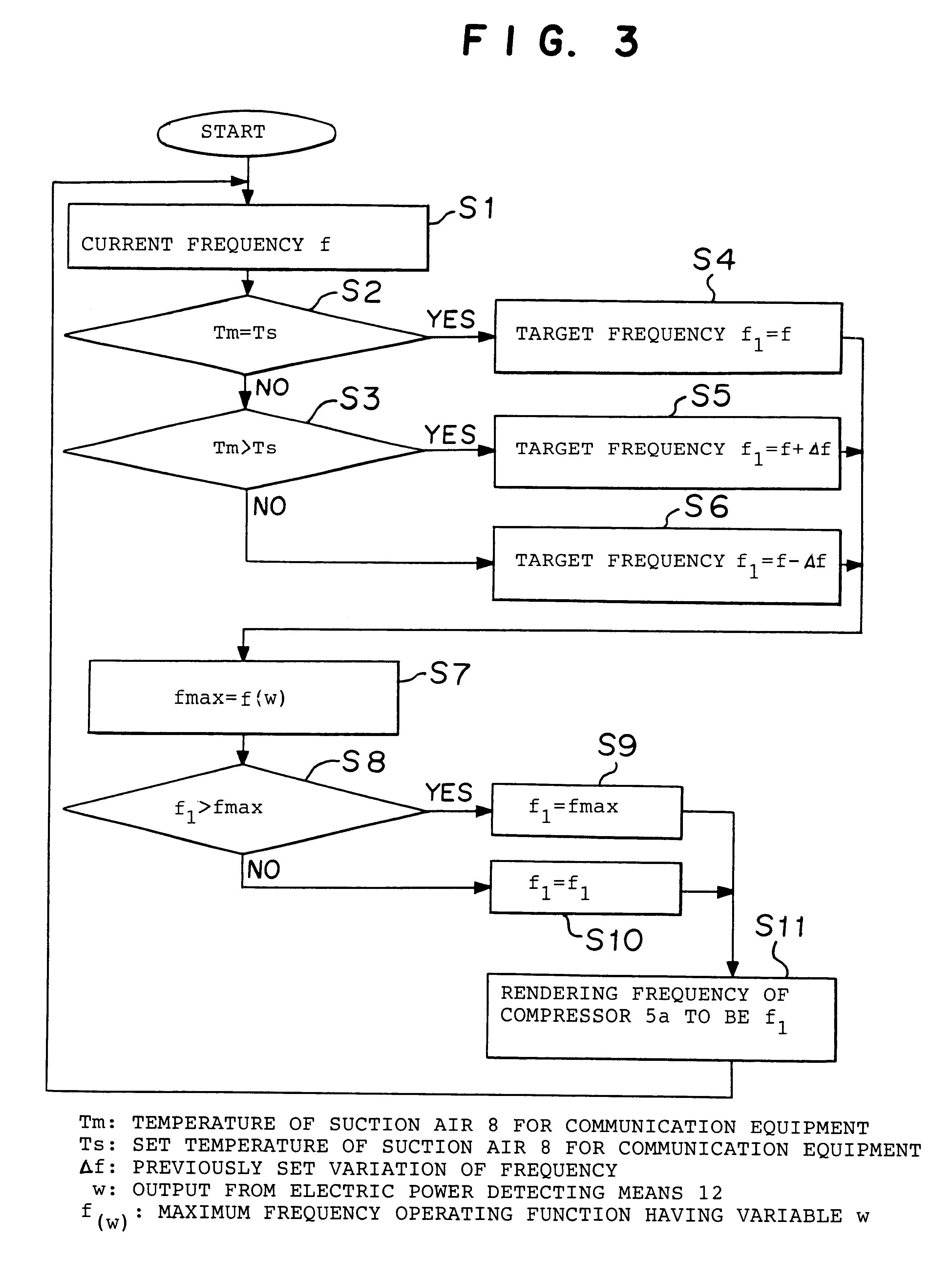
An operation of the cooling control method for the communication station according to Embodiment 6 will be described in reference of FIGS. 1 and 2. In the cooling control method for the communication station, the suction air temperature in the communication equipments 2 is controlled to be within a normal temperature by supplying a predetermined amount of the suction air 8 to the communication equipments 2 by the fan 4b. In general, the temperature of the suction air 8 is controlled to be 20.degree. C. or less. The suction air 8 is heated after cooling the communication equipments 2, sucked into the indoor unit 4 as the suction air 6, cooled by the indoor heat exchanger 4a, returned to the casing 10 as the blowing out air 7, and again provided to cool the communication equipments 2 as the suction air 8 for the communication equipments. The cooling control means 11a controls the temperature of the suction air 8 to be the set temperature, e.g. 20.degree. C., or less based on outputs f...

embodiment 7

Hereinbelow, an example according to Embodiment 7 of the present invention will be described.

FIG. 6 illustrates a structure of the cooling control method for the communication station according to Embodiment 7 of the present invention. FIG. 25 is a block chart illustrating the cooling control method according to Embodiment 7. In FIGS. 6 and 25, numerical references the same as in FIGS. 1 and 2 designate the same or similar portions and description of these portions is omitted. Numerical reference 11b designates the cooling control means for controlling the cooling capability of the air conditioner.

An operation of the cooling control method for the communication station according to Embodiment 7 will be described in reference of Figures. FIG. 26 is a flowchart illustrating an operation of the cooling control method 11b. A procedure until the steps S9 and S10 is similar to that in the examples of Embodiment 6. After calculating the frequency f, in the step S9 or S10, in step S31, a su...


PUM


Abstract

A cooling system for a communication station for cooling a casing of the communication relay station, accommodating communication equipments including heat components, by a boiling-type cooler in a natural circulation refrigerating circuit and an evaporator in a forced circulation refrigerating circuit, activated by a compressor comprising:a common airflow path having a heated air intake port for taking a heated air in the casing; anda common fan for sending an air to the boiling-type cooler and the evaporator,wherein the boiling-type cooler, the evaporator, and the common fan are built in a common airflow path.

Description

1. Field of the InventionThe present invention relates to a method for controlling to cool a communication station, wherein an inside of the communication station, accommodating communication equipments including heat elements such as boards, are cooled by a cooling device such as an air conditioner.The present invention also relates to an improvement of a system for cooling a casing of a communication station, wherein an inside of the casing, accommodating communication equipments including heat components, is cooled by a boiling type cooler in a natural circulation refrigerating circuit and an evaporator in a forced circulation refrigerating circuit, circulated by a compressor.2. Discussion of BackgroundIn recent years, communication stations including a large number of electronical boards for communication are located in various places for relaying communications along with expanding popularization of portable communication apparatuses. Dimensions of such communication relay stat...

Claims


Application Information

Patent Timeline
IPC IPC(8): F25D16/00F24F11/00F24F5/00H05K7/20F24F1/00
CPCF24F5/00F24F11/001F25D16/00H05K7/20354H05K7/2069H05K7/207F25B2500/06F25B2600/0253F25B2700/15Y02B30/741F25B2700/21172F25B2700/21151F24F11/30F24F2110/00Y02B30/70F24F1/06
Inventor ISAZAWA, KENJINONAKA, TAKASHISESHIMO, YU
Owner MITSUBISHI ELECTRIC CORP
Why Eureka
Try Eureka