System for clearing buried and surface mines

a mine and surface technology, applied in direction controllers, instruments, weapons, etc., can solve the problems of difficult deflagration/detonation of tnt fills or other fills, not being widely used, etc., and achieve the effect of short tim

Inactive Publication Date: 2003-04-01
LOCKHEED MARTIN ADVANCED PROJECTS
View PDF25 Cites 71 Cited by
  • Summary
  • Abstract
  • Description
  • Claims
  • Application Information

AI Technical Summary

Benefits of technology

Briefly stated, the invention allows a large number of anti-vehicle or antitank mines to be cleared in extremely short ti

Problems solved by technology

This approach, because of the time consumed in clearing mines and because of the design of mines with no metal elements, is not in as wide a use as before.
The reason that these approaches have

Method used


Image

  • System for clearing buried and surface mines
  • System for clearing buried and surface mines
  • System for clearing buried and surface mines

Examples


Embodiment Construction

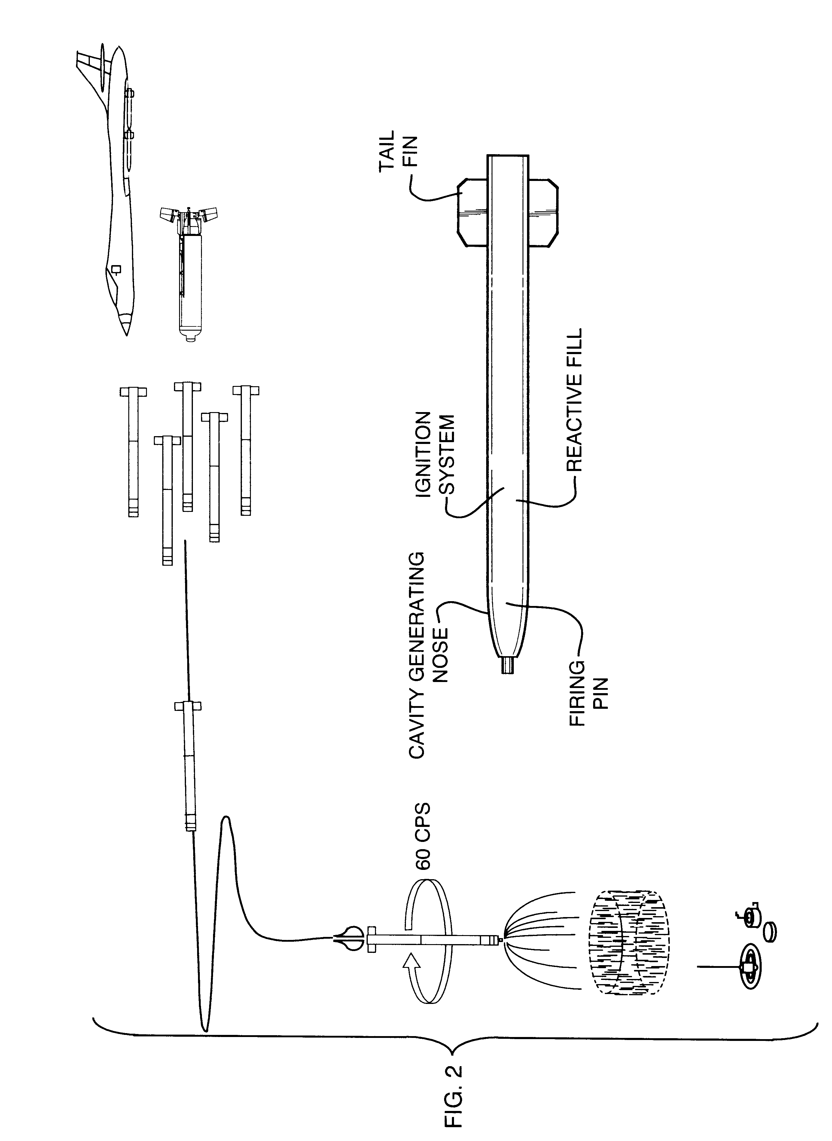
The concept to clear large numbers of buried and surface mines in a short time, in overview, includes the system and operation of the system, dart fill and cavity generating effects for the high temperature incendiary countermine dart and the dart ignition system.

System Concept

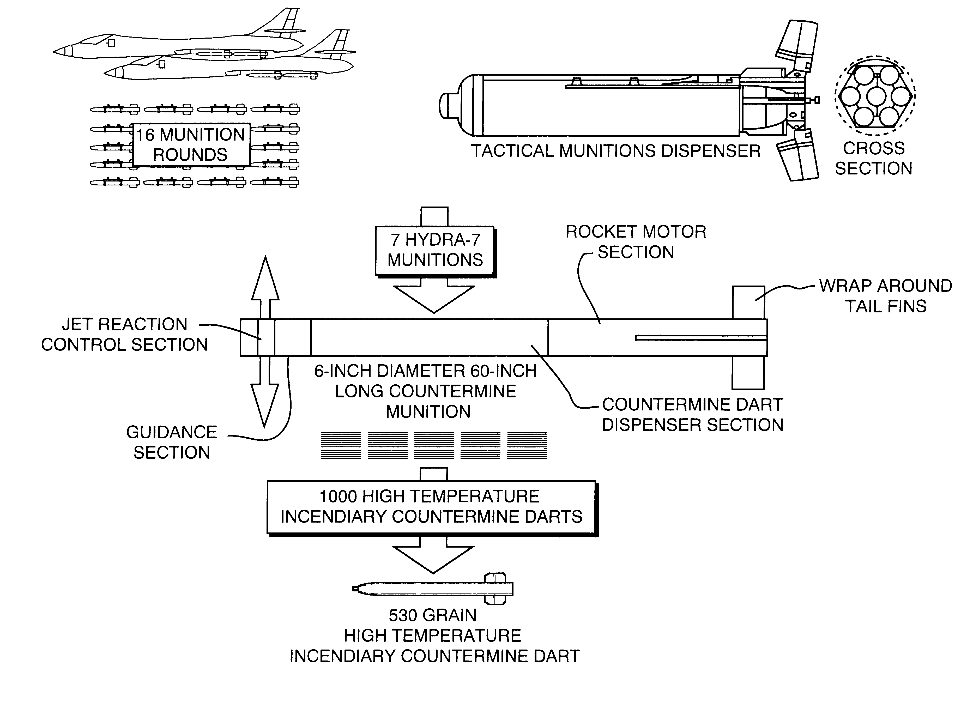
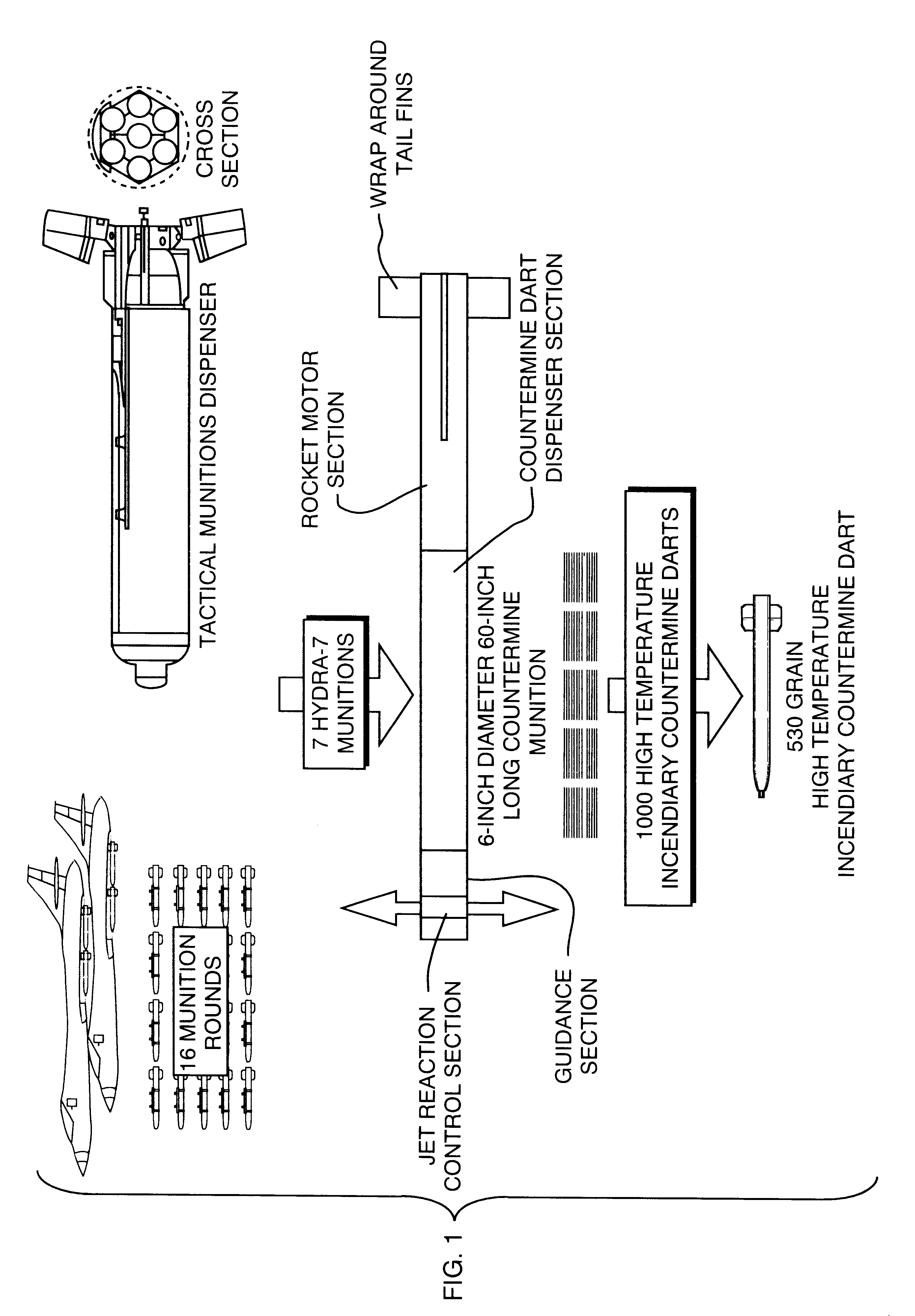
The system concept, using the air-delivered system as an example, typically comprises a tactical munitions dispenser packaging five 6-inch diameter, 60-inch long countermine munitions (FIG. 1). Each countermine munition contains 1,000 high temperature incendiary countermine flechettes or darts contained in a dispensing system located in the mid-body of the countermine munition. The countermine munition incorporates a GPS receiver and antenna system to allow signals from the GPS satellite constellation to be employed by the guidance logic of the countermine munition to determine its position relative to the GPS coordinates of the aimpoint over the minefield at which the rocket motor, located in the aft of the m...


PUM


Abstract

A method for deflagrating/detonating anti-tank and anti-vehicle land mines, beach zone mines, and surf zone mines located in mine belts or individually using delayed active ignition high temperature incendiary flechettes or darts.

Description

This invention relates to clearing by detonating or deflagrating anti-tank and anti-vehicle land mines located on the beach, or beach zone mines; located in the water near the surf line; or surf zone mines configured in mine corridors consisting of several mines or mine belts or individually. The invention allows the rapid clearing of large numbers of mines in an extremely short time or the clearing of mines "in stride" by amphibious forces or armored task force elements.The ability to clear beach zone and surf zone mines in support of amphibious operations allowing landing craft to move ashore to deposit combat forces is an offensive capability having high priority. The projection of power from the sea requires that mines be cleared in the beach zone and surf zone with a high probability of success in multiple landing zones in an extremely short time. Further, the ability to clear land mines by the maneuver elements or armored task forces to prevent the enemy from creating kill zon...

Claims


Application Information

Patent Timeline
IPC IPC(8): F41H11/00F41G7/34F42B12/60F42B12/02F42B12/44F41G7/00F41H11/12
CPCF41G7/346F42B12/60F42B12/44F41H11/12
Inventor MAYERSAK, JOSEPH R.BENEDICT, LANCE H.KRASS, ROBERT M.
Owner LOCKHEED MARTIN ADVANCED PROJECTS
Why Eureka
Try Eureka