
Electronic light emissive displays incorporating transparent and conductive zinc oxide thin film

a technology of conductive zinc oxide and light emissive displays, which is applied in the direction of discharge tubes with screens, discharge tubes luminescnet screens, discharge tubes, etc., can solve the problems of high operating voltage requirements of crt displays, large bulky form factor, and user may not be able to see the displayed information from an oblique viewing angl

Inactive Publication Date: 2003-04-01
TELEDYNE SCI & IMAGING
View PDF4 Cites 82 Cited by
  • Summary
  • Abstract
  • Description
  • Claims
  • Application Information

AI Technical Summary

Problems solved by technology

Unfortunately, CRT displays require high operating voltages and are too heavy for portable applications.
CRTs also have a large bulky form factor.
LCD panels also have a limited viewing angle so the user may not be able to see the displayed information from an oblique viewing angle.
Although the viewing angle for LCD displays has improved over the years, they are still inferior compared to CRTs and other emissive display technologies.
Another weakness of LCD displays is that the liquid crystal material response to a stimulus is intrinsically slow at low temperatures.
Thus, LCD displays are a poor choice for portable, automotive or military applications where operation at extreme low temperature may be required.
However, alkaline earth metals are extremely reactive and are not transparent.
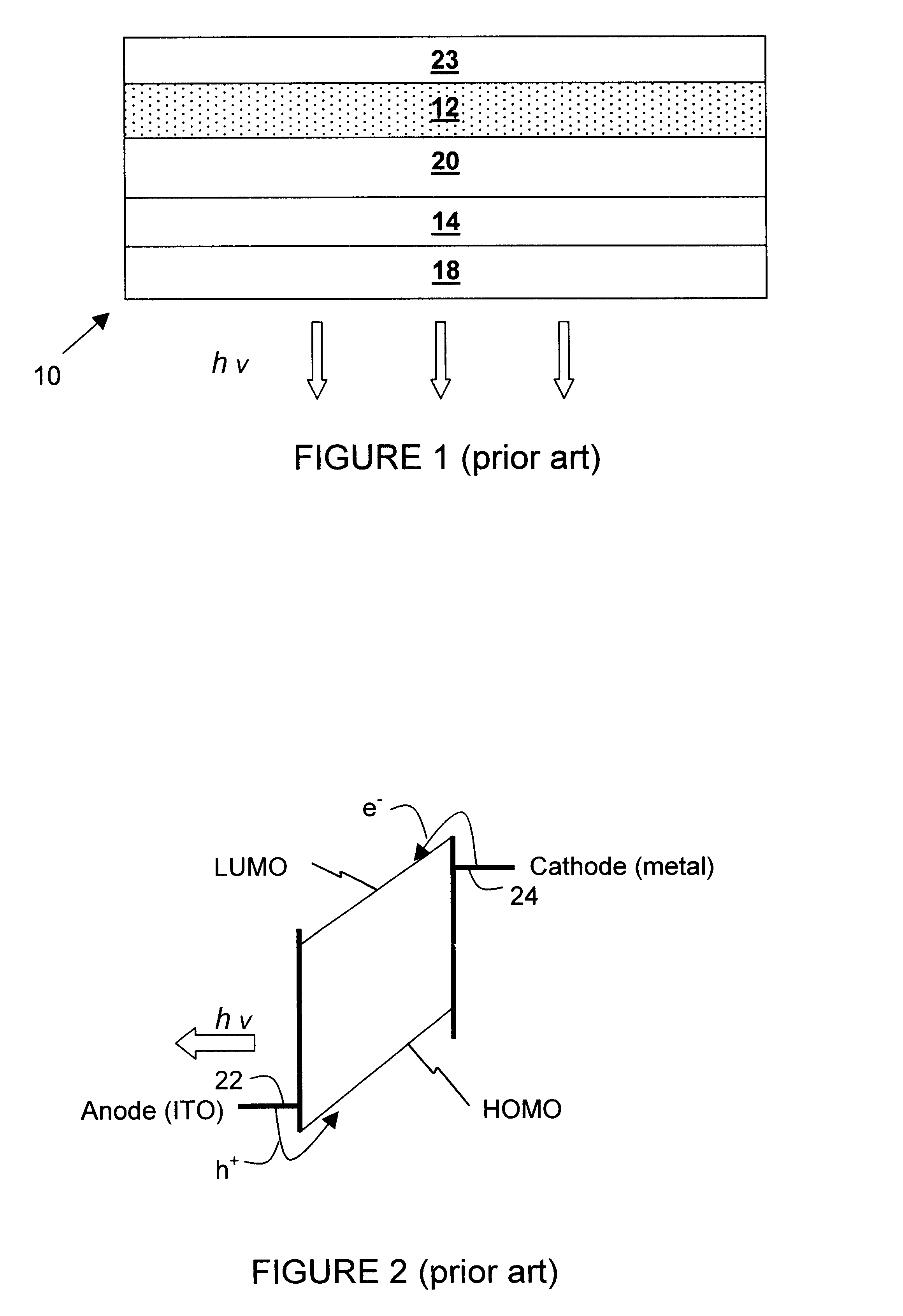
A significant problem with prior art displays is that the interface between the electrodes and the emissive medium creates energy barriers that must be overcome before charge can be injected into the medium.
In many prior art OLED devices, the imbalance in the ratio of hole injection and electron injection generates heat dissipation.
Such heating contributes to degradation of the medium and low efficiency of the OLED device.
However, the reactive cathode readily oxidizes and may degrade the organic medium interface.
Also, reactive metals are not compatible with the semiconductor processing technology and can degrade driving circuits on silicon substrates.
Accordingly, a complicated semiconductor manufacturing process involving barrier layers is required to combine the prior art OLED display device with electronic elements on a common substrate.
Unfortunately, prior art FEDs have an unacceptably short operational lifetime and require high operating voltages due to various material limitations related to the emitters.
Consequently, they have high work functions and require high operating voltages to generate sufficient field emitting electrons.
Furthermore, an insulating layer of oxide gradually forms on the emitter surface, increasing its work function and acting as a barrier to electron emission which results in decreasing luminance and uneven brightness of the displayed image over the life of the display.
Similar technical issues also impede the performance of vacuum microelectronics devices that mimic various types of vacuum tube electronic devices with individually gated solid-state micro electron emitters.

Method used


Image

  • Electronic light emissive displays incorporating transparent and conductive zinc oxide thin film
  • Electronic light emissive displays incorporating transparent and conductive zinc oxide thin film
  • Electronic light emissive displays incorporating transparent and conductive zinc oxide thin film

Examples


Embodiment Construction

In the following description of the preferred embodiment, reference is made to the accompanying drawings, which form a part hereof, and in which is shown by way of illustration specific embodiments in which the invention may be practiced. In the following description, numerous specific details are set forth in order to provide a thorough understanding of the present invention. It will be apparent to one skilled in the art that the present invention may be practiced without these specific details. In the development of any actual implementation, numerous implementation-specific decisions must be made to achieve the developers' goals, which will vary for each implementation. Accordingly, in order not to obscure the present invention, well-known structures and techniques are not shown or discussed in detail. Further, it should also be noted that the elements shown in the drawings herein are not necessarily to scale, the intent being to illustrate the relationship of the elements.

The pr...


PUM


Abstract

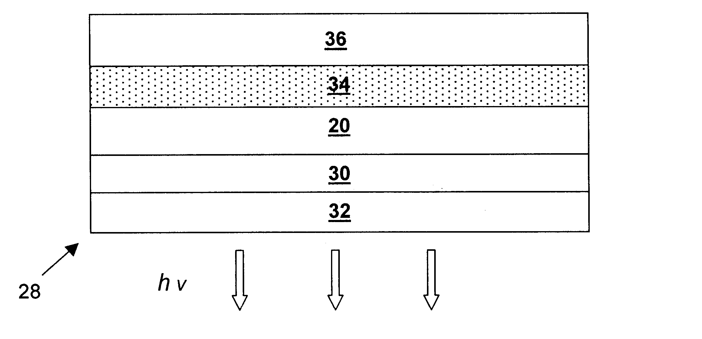
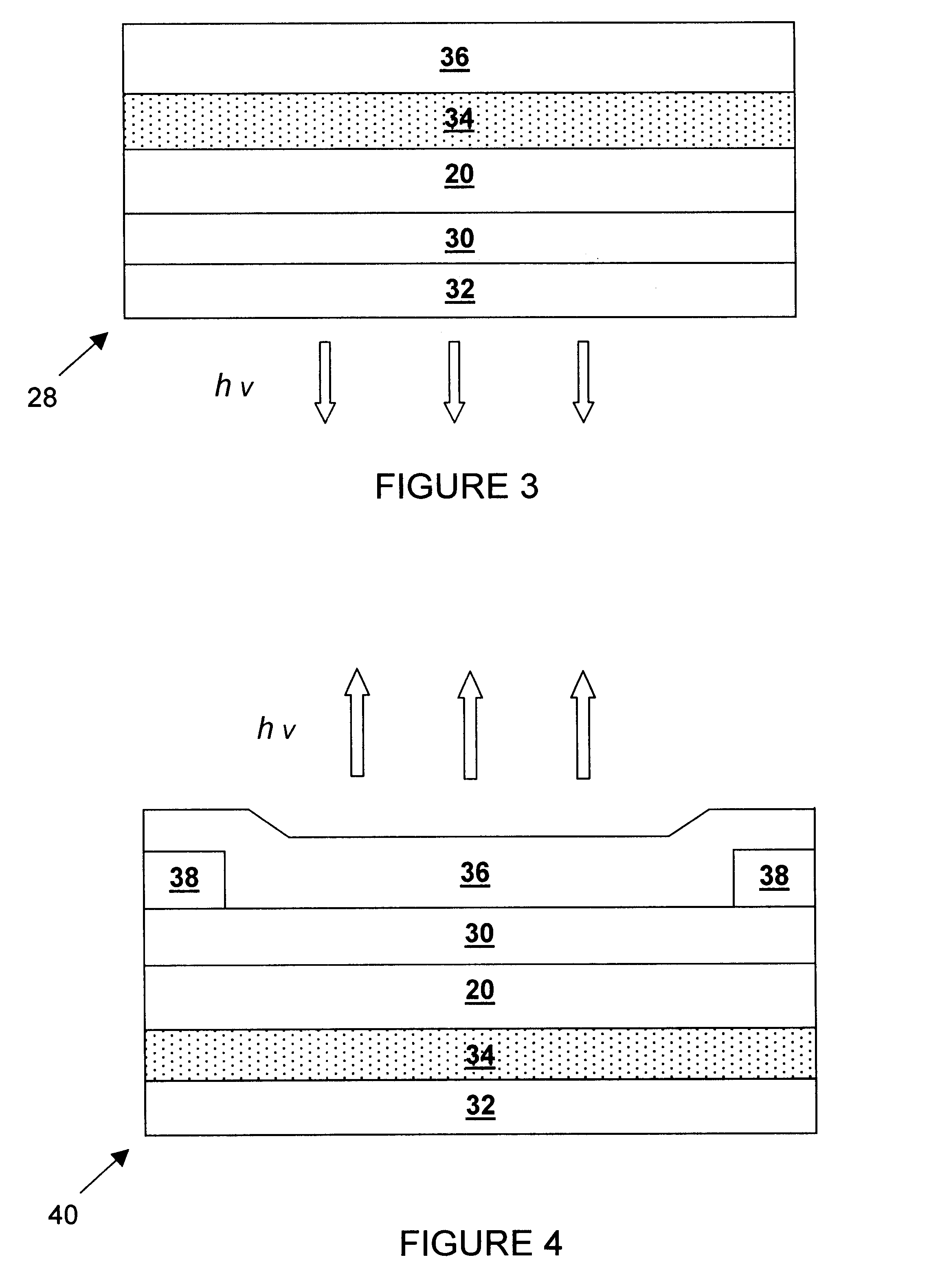
The present invention provides co-doped zinc oxide to flat panel, light emissive display devices and vacuum microelectronic devices to improve their efficiency and lifetime. This material has a low growth temperature and is compatible with metal oxide semiconductor (MOS) processing technology. It is tranparent, chemically stable and has a low work function, which result in many advantages when being used as the cathode for the aforementioned devices. In one embodiment of the emissive display device, an organic light diode (OLED) display has a high work function metal anode, such as platinum (Pt), gold (Au) or nickel (Ni) and a low work function co-doped zinc oxide cathode. Because of the energy level alignment provided by these two materials, the potential energy barriers to injection of electrons from the cathode and holes from the anode into the organic emissive medium are minimized so the display device operates more efficiently.

Description

1. Field of the InventionThe present invention relates to the applications of co-coped n-type zinc oxide thin film as a chemically stable and low work function cathode to Organic Light Emissive Diode (OLED) display, Field Emission Display (FED) and vacuum microelectronic display devices.2. Description of Related ArtDisplay devices are a fast growing segment of the electronics market. Historically, commercially viable displays have relied on cathode ray tube (CRT) and liquid crystal display (LCD) technologies due to reliability and affordability. CRT technology is mature and able to achieve high resolution, high luminance (brightness), low cost and long life. Unfortunately, CRT displays require high operating voltages and are too heavy for portable applications. CRTs also have a large bulky form factor. More recently, flat panel LCDs have gained acceptance in many applications since they operate at power levels compatible with battery operation, are lightweight and have a thin form f...

Claims


Application Information

Patent Timeline
Patent Type & Authority Patents(United States)
IPC IPC(8): H01J1/304H01J1/30H01L51/52H01L51/50H05B33/26H01J29/04H01J31/12H01L27/32H05B33/02
CPCH01J1/304H01L27/32H01L51/5221H01L51/5234H01L2251/5323H01L51/529H01L2251/5315H10K2102/3026H10K2102/3031H10K59/873H10K59/80524H10K59/00H10K50/828H10K50/87
Inventor CHEUNG, JEFFREY T.WILLIAMS, GEORGE M.WARREN, JR., LESLIE F.ZHUANG, ZHIMING
Owner TELEDYNE SCI & IMAGING
Learn More