Waist-mounted evaporative personal cooler

a technology of evaporative personal cooler and fan, which is applied in the direction of domestic cooling apparatus, heating types, separation processes, etc., can solve the problems of increasing heat and exhaustion, affecting the cooling effect, and wet user's clothing,

Inactive Publication Date: 2003-04-08
STRAUSS TED
View PDF10 Cites 78 Cited by
  • Summary
  • Abstract
  • Description
  • Claims
  • Application Information

AI Technical Summary

Problems solved by technology

They require the user to hold a device or to do something to get its benefit (which is not only bothersome, but such activity can generate more heat and exhaustion)
They wet the user's clothing
They provide relatively poor cooling power
However, this device is not as affordable as would be desirable, creates a bothersome humming noise close to the ears, and makes a questionable fashion statement.
Still, each of these methods has serious drawbacks for the average user due to cost, complexity, and / or lack of effectiveness over time.
This approach has several major disadvantages: 1) it wets the user's shirt, 2) because it blows over the user's shirt, it either doesn't cool the user's torso or requires the user to remove his or her shirt to receive its benefit, 3) it destroys the user's hairdo, and 4) it is bulky, unattractive, and relatively expensive.

Method used


Image

  • Waist-mounted evaporative personal cooler
  • Waist-mounted evaporative personal cooler
  • Waist-mounted evaporative personal cooler

Examples


first alternative embodiment (fig.4)

Operation of First Alternative Embodiment (FIG. 4)

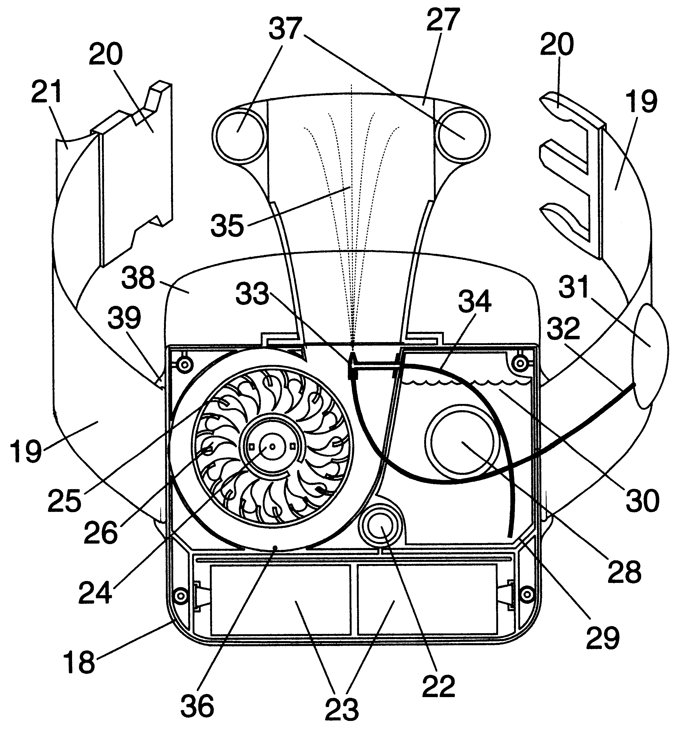
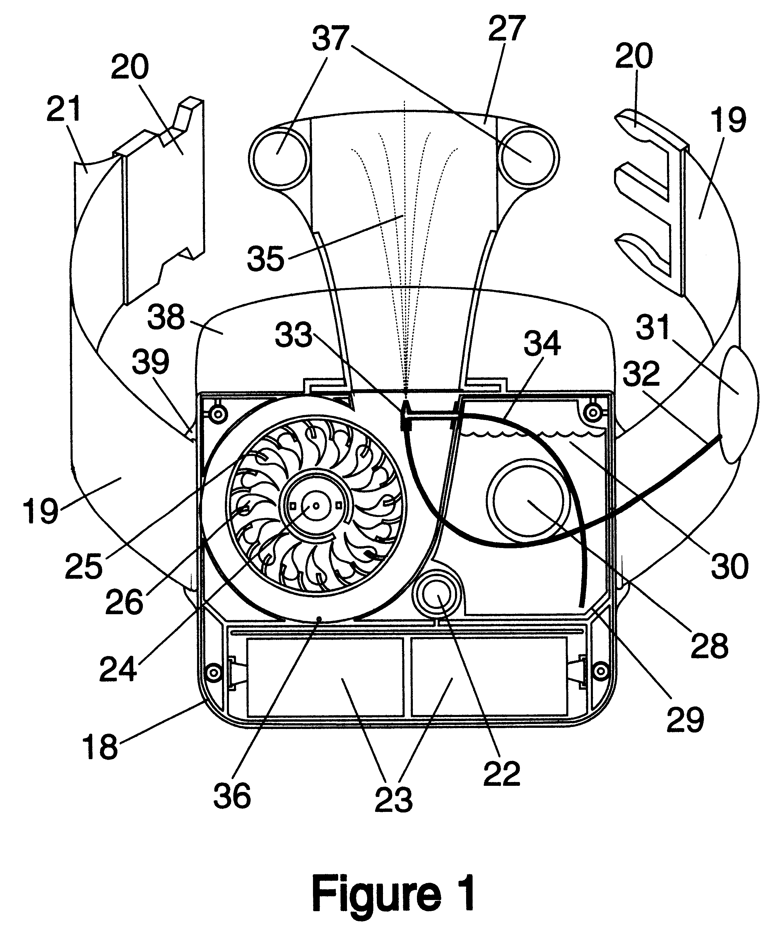
When the user presses bulb 31, air is forced through tube 32, which partly inflates balloon 40. As balloon 40 expands, pressure is transmitted into reservoir 29, causing water to move through tube 34, propelling it into blower impeller 25. This breaks the water stream into tiny droplets, which in turn are propelled with the upward moving air through exhaust duct 27 and onto the user's skin.

Balloon 40 is also used to prevent water in reservoir 29 from backing into air tube 32. In a variation on this approach, a spray nozzle is provided at the blower end of tube 34. This atomizes the water before it hits the impeller, breaking the spray into even finer droplets.

In a related approach, balloon 40 can be eliminated by incorporating a one-way or check valve into bulb 31 so that air can only move from bulb 31 toward water reservoir 29, and not in the reverse direction.

In another variation, the blower impeller has a narrow ring of small plas...

second alternative embodiment (fig.5)

Operation of Second Alternative Embodiment (FIG. 5)

In this embodiment, when the user presses bulb 31, air in tube 32 is forced into atomizer 33, which dispenses spray 35 directly to the skin of the user's back. An advantage of this approach is that none of the water is wasted accumulating on the inside of exhaust duct 27. Another advantage is that as the batteries wear down and the stream of forced air becomes less powerful, the spray still reliably reaches the point or points on the user's skin that are found to be most useful.

Description of Third to Fifth Alternative Embodiments (FIGS. 6a-c)

This group of alternative embodiments makes use of a small electric pump 42 to move water, enabling automated delivery of the water spray. Pump 42 may be of any variety, such as centrifugal, peristaltic, diaphragm, piston, etc. All of these variations use a blower switch 43 to turn on blower motor 24 and a momentary contact switch 44 to activate electric pump 42.

Operation of Third to Fifth Alte...


PUM

PropertyMeasurementUnit
pressureaaaaaaaaaa
poweraaaaaaaaaa
attractiveaaaaaaaaaa

Abstract

A waist-mounted evaporative personal cooling device designed to cool the back of a user, comprises a blower (25), a liquid reservoir (29), a means to deliver liquid from the reservoir a mist of droplets into blower-forced air (33) or directly onto the skin area to which the forced air will be directed (45), and a duct (27) to guide forced air under the user's shirt or blouse and directly onto or across the skin of the user's back. The device improves on prior art coolers by delivering a powerful evaporative cooling effect directly to a user's back, while being compact, comfortably wearable, and requiring the user to do little or nothing to get its benefit.

Description

1. Field of InventionThis invention relates to the field of personal comfort devices, specifically to evaporative personal cooling devices.2. Prior ArtThroughout history, people have used various methods to keep themselves cool on hot days and in hot environments, especially when engaged in strenuous activities. Simple methods of personal cooling include wearing a moistened bandanna around one's neck, shading oneself with a hat or parasol, fanning oneself, and using portable misting devices. All of these have at least one of the following disadvantages:They require the user to hold a device or to do something to get its benefit (which is not only bothersome, but such activity can generate more heat and exhaustion)They wet the user's clothingThey provide only short-term reliefThey provide relatively poor cooling powerU.S. Pat. No. 5,802,8 of Ted N. Strauss (granted Sep. 8, 1998) shows a cooler that uses a wind-chill effect within the device and delivers the resulting coolness to the ...

Claims


Application Information

Patent Timeline
Patent Type & Authority Patents(United States)
IPC IPC(8): A61F7/00F24F5/00A62B17/00A61F7/02
CPCA61F7/00F24F5/0035A41D13/0056A61F7/007A61F2007/0024A61F2007/0063Y02B30/545A61F2007/0094A61F2007/0228A62B17/005A61F2007/0065Y02B30/54
Inventor STRAUSS, TED
Owner STRAUSS TED
Why Eureka
Try Eureka