Power conditioning for model railroad control decoders

a technology of power conditioning and control decoder, which is applied in the direction of electric variable regulation, process and machine control, instruments, etc., can solve the problems of low efficiency rectifier devices limiting the available miniaturization, and achieve the effects of improving current capacity and reliability, improving power management efficiency, and small siz

Inactive Publication Date: 2003-04-08
IRELAND ANTHONY J
View PDF5 Cites 23 Cited by
  • Summary
  • Abstract
  • Description
  • Claims
  • Application Information

AI Technical Summary

Benefits of technology

Improvements in power management efficiency of full bridge rectifiers described in this invention allow creation of decoders with improved current capacity and reliability, in a smaller size.

Problems solved by technology

Shrinking the physical size of conventional decoder designs using the prior art leads to configurations where full bridges implemented with low efficiency rectifier devices limit the available miniaturization because of thermal limitations.

Method used


Image

  • Power conditioning for model railroad control decoders
  • Power conditioning for model railroad control decoders
  • Power conditioning for model railroad control decoders

Examples


Embodiment Construction

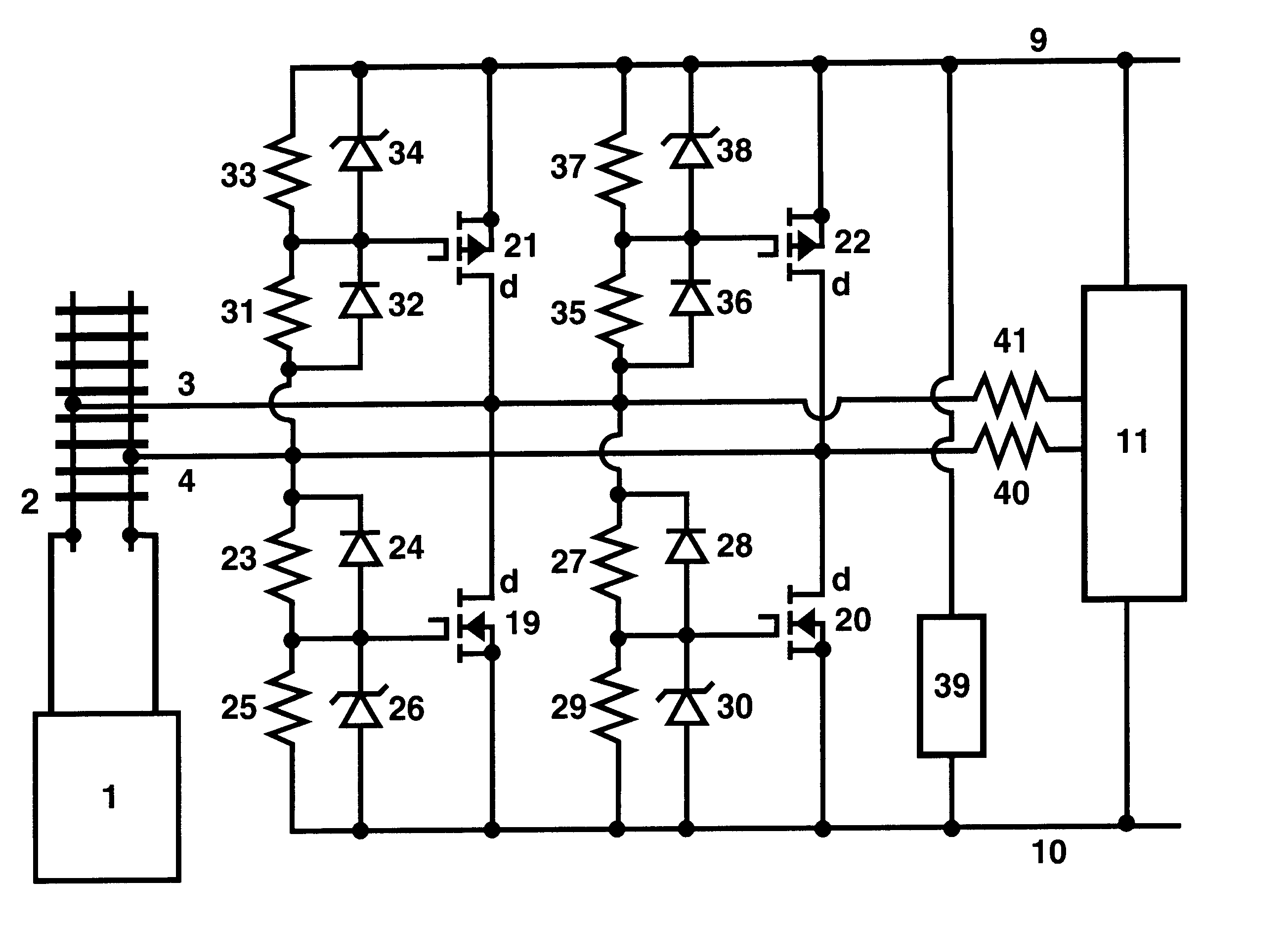
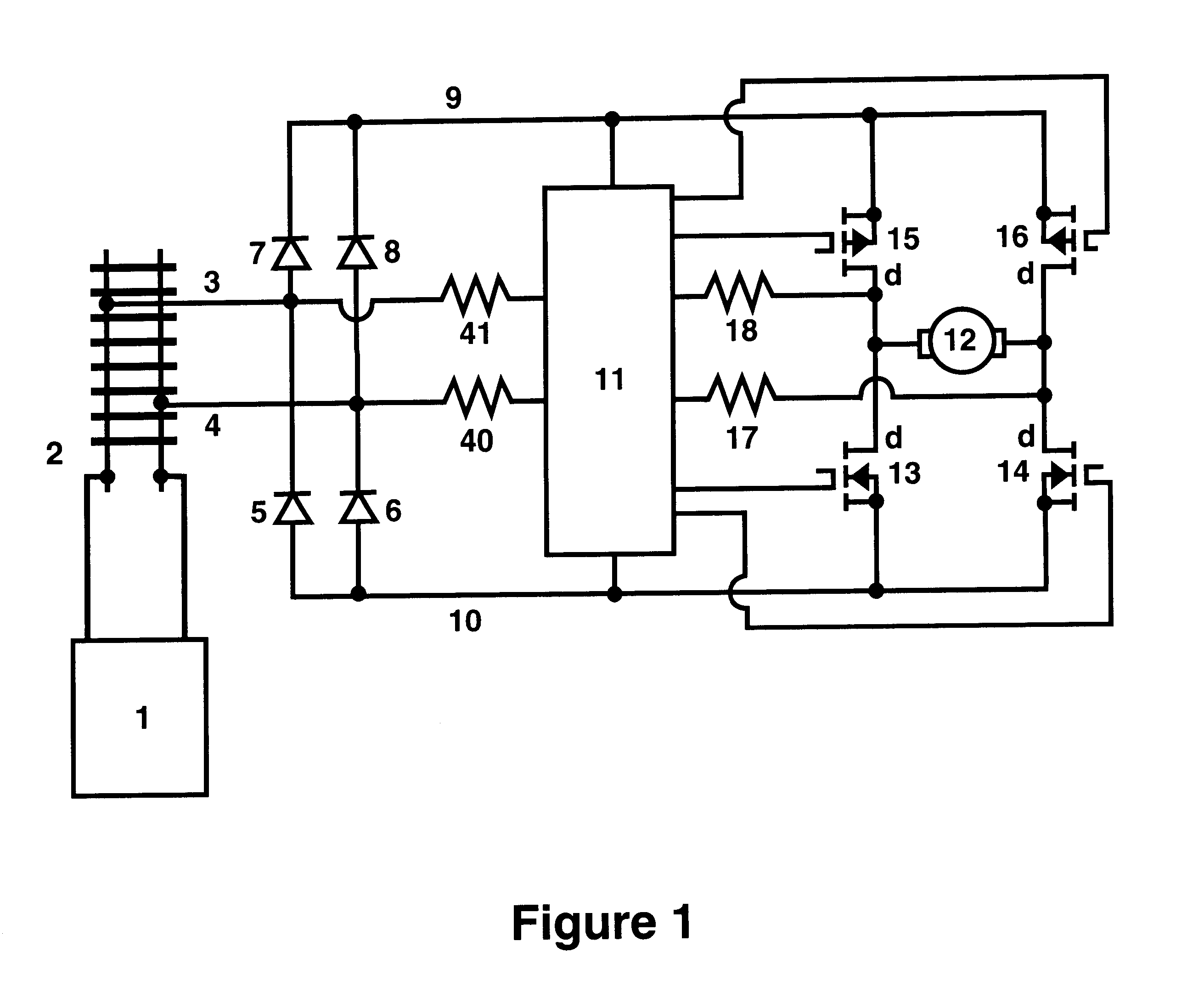
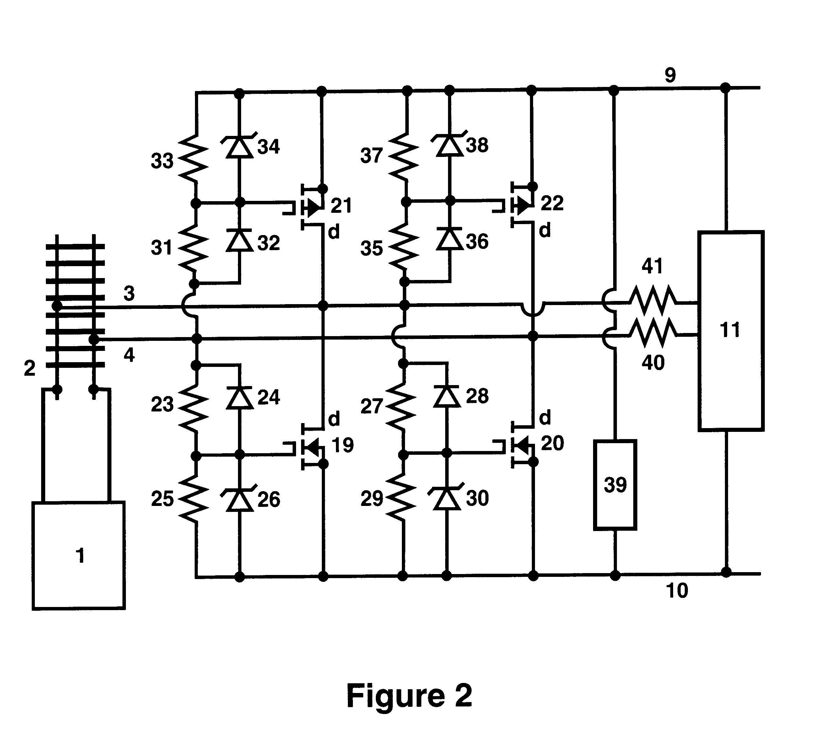
FIG. 1 depicts the key elements of a typical decoder designed using prior art. Item 1 represents the power driving, or output, stage of a control system that supplies encoded voltage waveforms that are conducted to a model railroad layout, 2, to control devices connected to the layout.

Items 5 through 18 represent many important elements incorporated into a prior art decoder design. Items 3 and 4 represent the power input connections from the decoder to the track or layout, 2, and system. These input connections may be wheel pickups or even a directly wired connection. Items 5 and 6 represent two rectifier diodes that conduct current as the negative bridge output to the internal decoder negative node, 10.

Node 10 is typically the reference point for voltage and polarity for the decoder and also this commentary. Items 7 and 8 represent two rectifier diodes that conduct current as the positive bridge output to the internal decoder positive node, 9. These four items 5,6,7,8 are shown as ...


PUM


Abstract

New techniques are presented for increased power handling capability for model railroad decoders and other attached electronics when space and cooling limitations exist. Additionally, novel usage of existing electronic voltage measurements permit an improvement in Overcurrent fault detection and recovery. These techniques allow new designs with improved reliability and load current capacity.

Description

BACKGROUND OF INVENTIONThis invention pertains to the field of control systems for scale model railroad layouts, and specifically to improvements in power handling capacity of decoders used for control of elements around the layout.Modern layout control systems allow the simultaneous control of many devices using decoder devices that are attached to or run on the tracks of model railroads. The ability to make smaller, less expensive and more reliable decoders is of great benefit, allowing the usage of the control technology in smaller railroad components and allowing greater flexibility in packaging design and installation.The decoders derive power and control information via at least a two conductor electrical connection to the control system. This connection may be via wheel or slider pickups from the tracks, overhead catenary wires or any other conductive connection to the layout control system. The decoder analyses the encoded voltage waveform or signal conducted from this contr...

Claims


Application Information

Patent Timeline
Patent Type & Authority Patents(United States)
IPC IPC(8): H02M7/12
CPCH02M7/125A63H19/24
Inventor IRELAND, ANTHONY J.
Owner IRELAND ANTHONY J
Why Eureka
Try Eureka