Heating and cooling system using frictional air heating

a technology of frictional air heating and cooling system, which is applied in the direction of fluid friction for heating, heating types, stoves or ranges, etc., can solve the problems of shortening the overall life of the motor, limiting the extent to which the temperature of the air passing through the enclosure can be increased, and compromising the efficiency of prior art devices. , to achieve the effect of efficient utilization

Inactive Publication Date: 2003-04-15
DAVIS MAXIE C
View PDF6 Cites 10 Cited by
  • Summary
  • Abstract
  • Description
  • Claims
  • Application Information

AI Technical Summary

Benefits of technology

It is another object of the present invention to provide a frictional heating system which efficiently utilizes a single motor to simultaneously operate not only the turbines used to frictionally heat air inside the heating assembly, but also an intake fan used to draw ambient air from a building through a heating and cooling system used in conjunction with the frictional heating system.
It is another object of the present invention to provide a frictional heating system which uses a conduit system which interconnects the air-cooling condenser coil of a conventional cooling system in a manner such that the heat generated from the condenser coil during operation is directed back into the cooling system and efficiently utilized, thereby permitting the condenser coil to be completely enclosed within the interior of a building rather than having to be positioned outside of the building so that the heat generated by the condenser coil can dissipate into the open air.

Problems solved by technology

Placing the motor and turbine together within such a confined space can cause the motor to overheat, which not only severely impairs the performance of the prior art frictional heating devices, but also drastically shortens the overall life of the motors.
Furthermore, using only one turbine within a single enclosure compromises the efficiency of prior art devices by limiting the extent to which the temperature of the air passing through the enclosure can be increased.

Method used


Image

  • Heating and cooling system using frictional air heating
  • Heating and cooling system using frictional air heating
  • Heating and cooling system using frictional air heating

Examples


Embodiment Construction

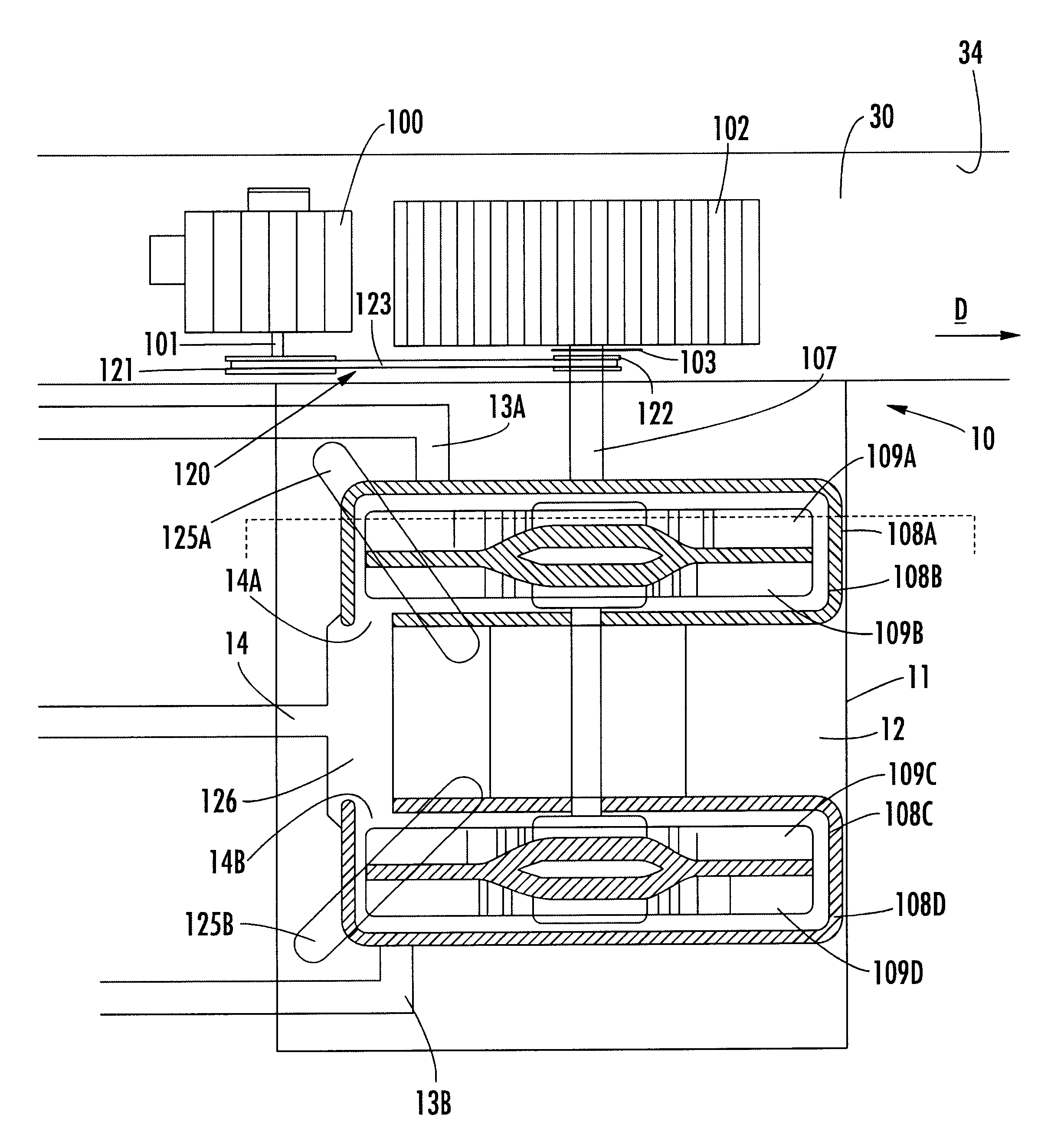
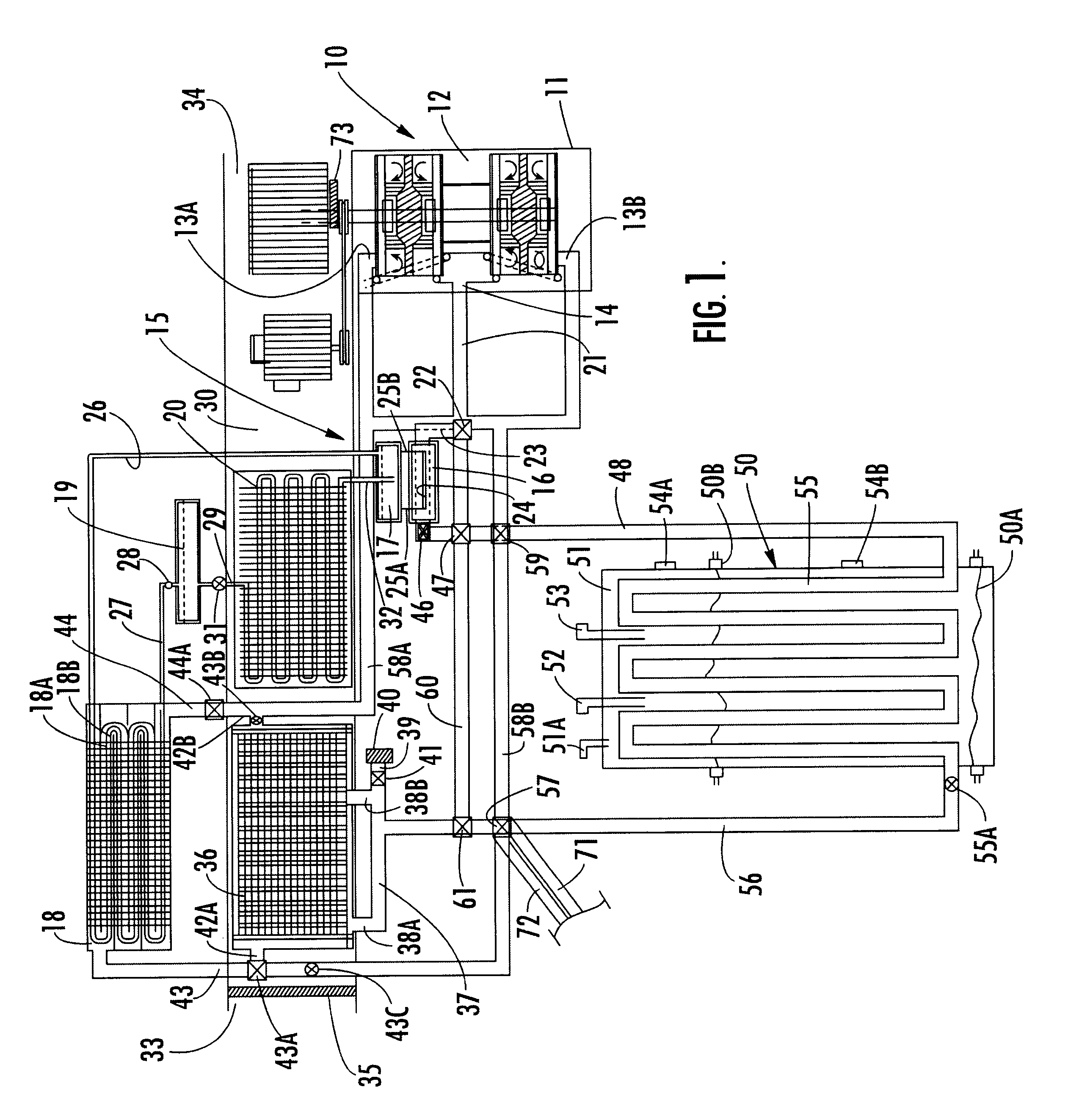
Referring now to the drawings, a frictional heating and cooling system according to the present invention is illustrated in FIG. 1 and shown generally at reference numeral 10. The heating and cooling system 10 includes an enclosure 11 defining an interior 12, which is in fluid communication with air inlet manifolds 13A and 13B, and an air outlet manifold 14. Air is drawn through the air inlet manifolds 13A and 13B into the interior 12, and is discharged therefrom through the air outlet manifold 14 after being heated within the interior 12. As discussed in detail below, the air is heated within the interior 12 to a temperature of between 140.degree. F. to 460.degree. F., and is discharged from the enclosure 11 through the air outlet manifold 14 at a high volumetric rate. A number of dispatch and directional valves are positioned throughout the frictional heating and cooling system 10 and cooperate together to control the passage of air through the system 10 to ensure, among other thi...


PUM


Abstract

A frictional heating system for communicating with an air supply duct to heat and cool air in a building, including an enclosure defining an interior, two air inlets, and at least one air outlet therein communicating with the interior of the enclosure for permitting air flow therethrough. A plurality of turbines are carried on a common shaft for rotation therewith. Each of the turbines is positioned within the enclosure for drawing air into the enclosure and frictionally heating the air therein. A first conduit is in fluid communication with the air outlet, a water heater and an air conditioning system, for moving frictionally-heated air from the air outlet to one or the other of the water heater and the air conditioning system. A motor assembly including a motor is operatively connected to the common shaft and positioned outside the enclosure for driving the common shaft and turbines.

Description

TECHNICAL FIELD AND BACKGROUND OF THE INVENTIONThis invention relates to a frictional heating assembly for use with a heating and cooling system, and a water heater. In particular, the application discloses a frictional heating system wherein enhanced heating efficiency and operation is achieved by sequentially passing air through multiple turbine housings. A rotating turbine is positioned in each of the turbine housings. The turbines generate mechanical energy during operation which is converted into heat energy that heats the air passing through the housings.Prior art patents disclose the concept of frictionally heating air by using a single turbine which is driven by a motor positioned together within the same enclosure in which the air is frictionally heated. Placing the motor and turbine together within such a confined space can cause the motor to overheat, which not only severely impairs the performance of the prior art frictional heating devices, but also drastically shortens...

Claims


Application Information

Patent Timeline
Patent Type & Authority Patents(United States)
IPC IPC(8): F24J3/00
CPCF24J3/003F24V40/00
Inventor DAVIS, MAXIE C.
Owner DAVIS MAXIE C
Why Eureka
Try Eureka