
Methods and apparatus for splitting, imaging, and measuring wavefronts in interferometry

a wavefront imaging and wavefront technology, applied in the field of interferometry, can solve the problems of high magnification, high cost, and complex system, and achieve the effect of avoiding the complexity of multi-camera systems

Inactive Publication Date: 2003-04-22
METROLASER
View PDF40 Cites 44 Cited by
  • Summary
  • Abstract
  • Description
  • Claims
  • Application Information

AI Technical Summary

Benefits of technology

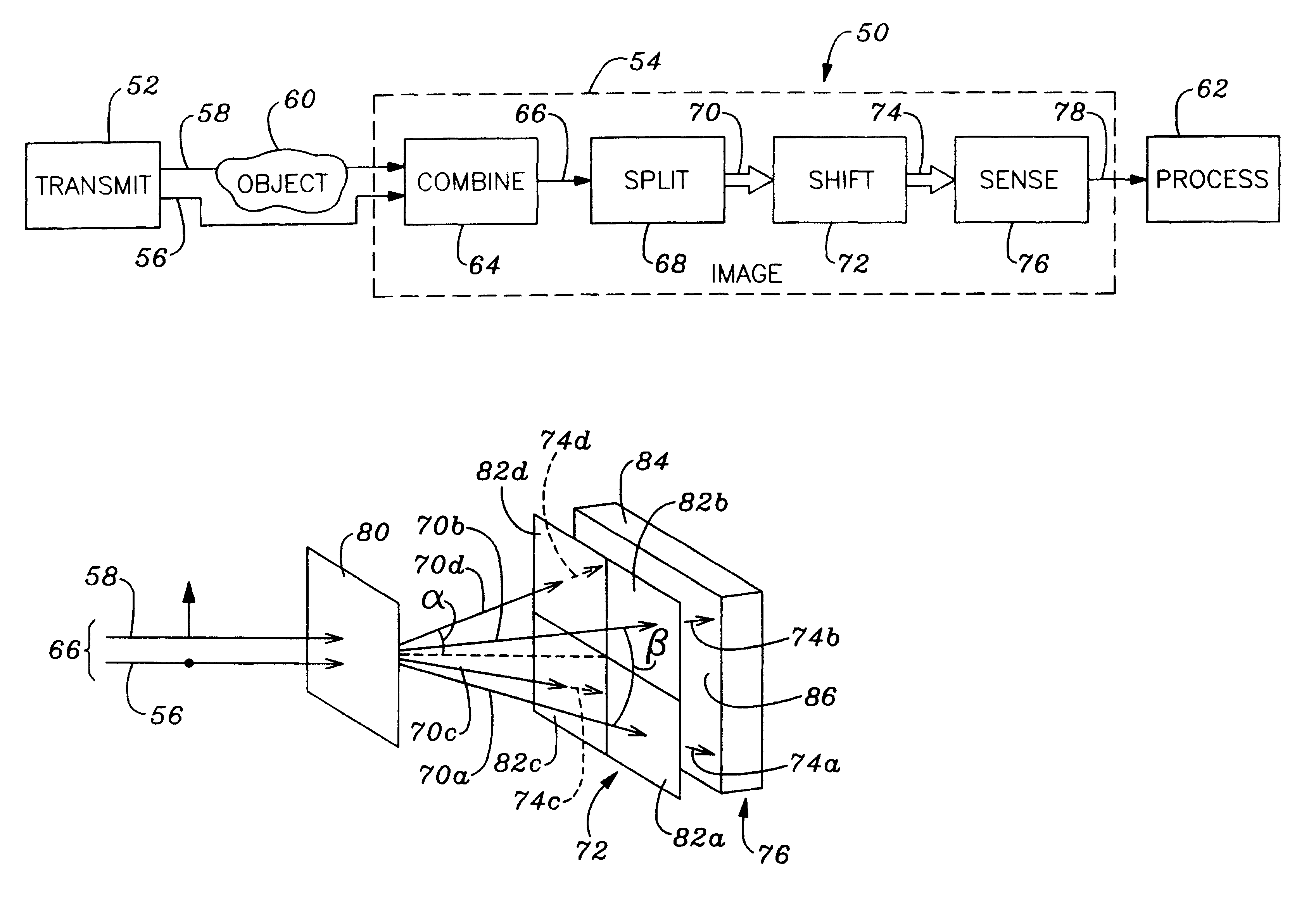
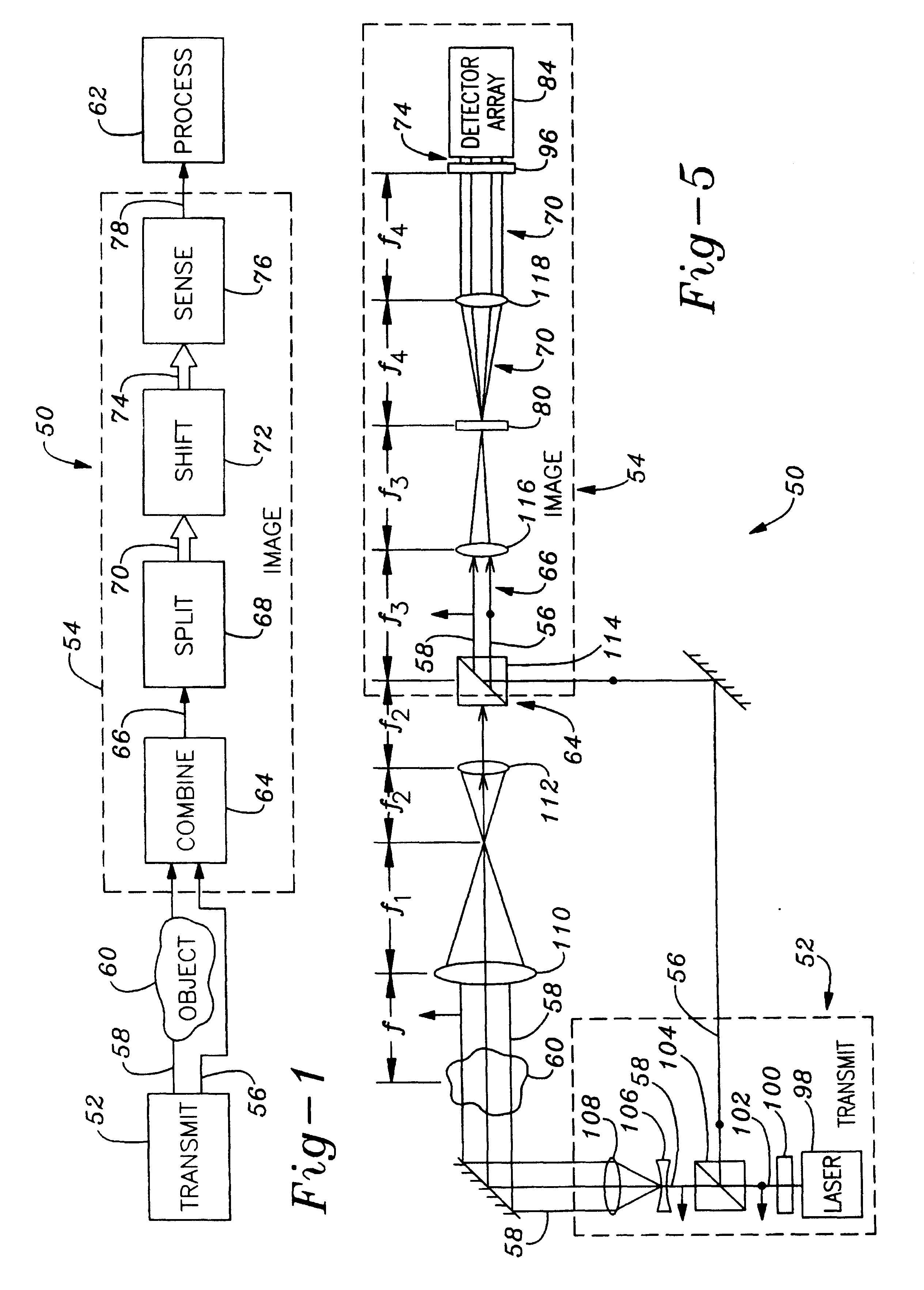
It is one object of the present invention to provide an interferometric wavefront sensor that incorporates spatial phase shifting but avoids the complexity of multi-camera systems by using a single two-dimensional pixilated detector, such as a standard charge coupled device (CCD) camera.
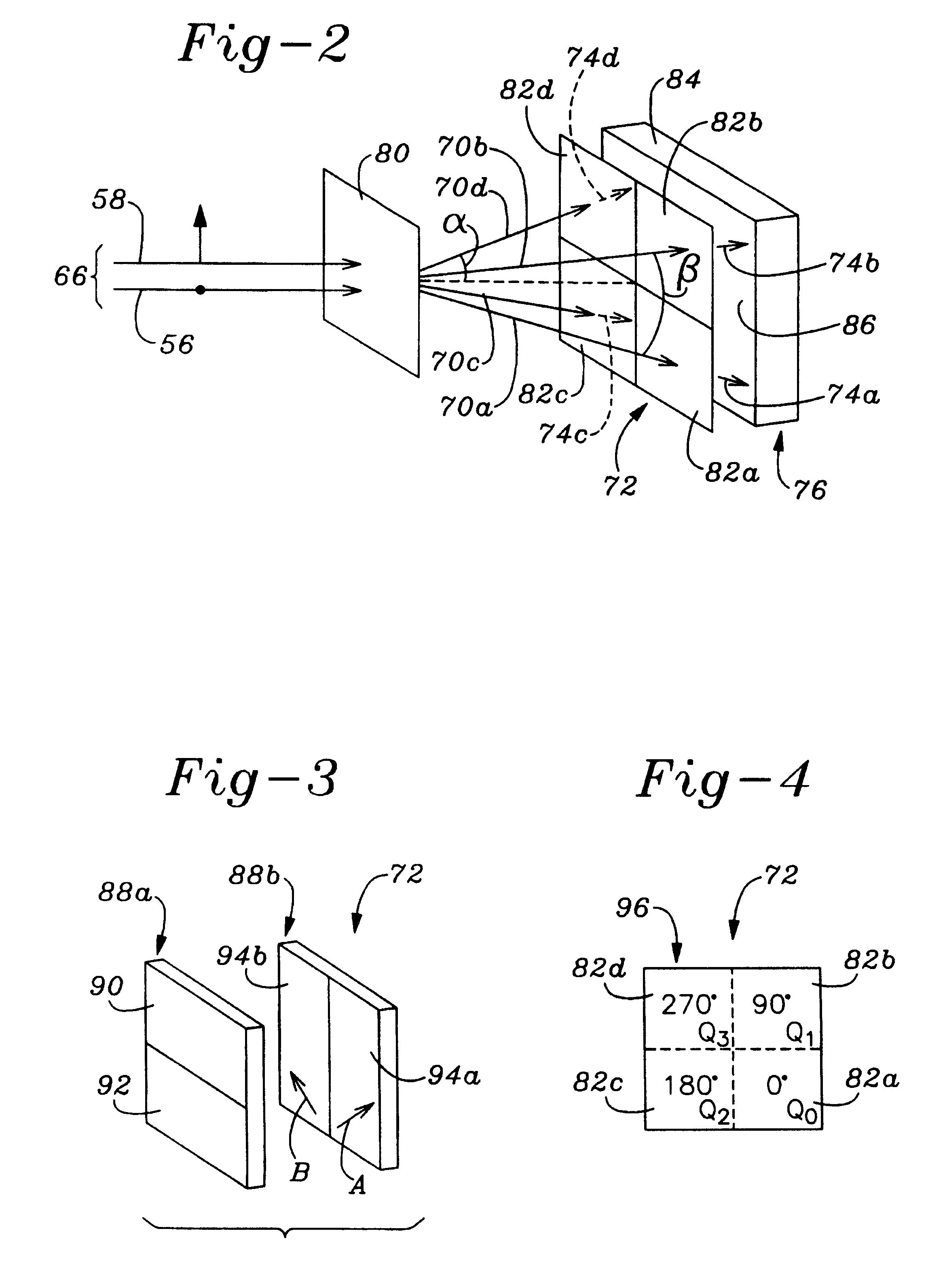
It is yet another object of the invention to provide methods and apparatus for dividing an incoming wavefront into four sub-wavefronts that are imaged substantially contiguous to maximize the coverage of a pixilated area detector, while minimizing the number of necessary optical components to provide a compact system.

Problems solved by technology

One of the disadvantages of these methods is that multiple cameras are required and complicated optical arrangements are need to produce the phase-shifted images, resulting in expensive complex systems.
However, one of the disadvantages of these grating methods is that careful adjustment of the position of the grating is required to control the phase step between the beams.
This method requires the phase of the object field to vary slowly with respect to the detector pixels; therefore, using this method with speckle fields requires high magnification.
This method has a number of drawbacks, including the inability to measure of wavefronts (i.e., the spatial phase distribution across the profile of a beam) and to form contiguous images on a single pixilated detector such as a standard charge coupled device (CCD).
These types of sensors are disadvantageous in that they typically have much less sensitivity and spatial resolution than interferometric wavefront sensors and are not capable of performing relative phase measurements such as two-wavelength interferometry.

Method used


Image

  • Methods and apparatus for splitting, imaging, and measuring wavefronts in interferometry
  • Methods and apparatus for splitting, imaging, and measuring wavefronts in interferometry
  • Methods and apparatus for splitting, imaging, and measuring wavefronts in interferometry

Examples


Embodiment Construction

The present invention provides apparatus and methodology for measuring various parameters of test objects by simultaneously generating multiple phase-shifted images. More particularly, the apparatus and methodology of the present invention enable multiple phase-shifted images (or interferograms) to be obtained with a single imaging device and by a single pulse of a laser and at very high rates. In doing so, the present invention splits, images, and measures a wavefront made up of a reference and an object wavefront from an object under test.

The apparatus of the present invention may be configured to measure--in situ and in real time--flow parameters in a multiphase environment. Examples of such flow parameters include the concentrations of selected gaseous species, temperature distributions, particle and droplet distributions, density, and so on. In addition to flow parameters, the apparatus of the present invention may be configured to measure the displacement (e.g., the vibration)...


PUM

PropertyMeasurementUnit
aspect ratioaaaaaaaaaa
divergence anglesaaaaaaaaaa
surface areaaaaaaaaaaa

Abstract

Apparatus for splitting, imaging, and measuring wavefronts with a reference wavefront and an object wavefront. A wavefront-combining element receives and combines into a combined wavefront an object wavefront from an object and a reference wavefront. A wavefront-splitting element splits the combined wavefront into a plurality of sub-wavefronts in such a way that each of the sub-wavefronts is substantially contiguous with at least one other sub-wavefront. The wavefront-splitting element may shift the relative phase between the reference wavefront and the object wavefront of the sub-wavefronts to yield a respective plurality of phase-shifted sub-wavefronts. The wavefront-splitting element may then interfering the reference and object wavefronts of the phase-shifted sub-wavefronts to yield a respective plurality of phase-shifted interferograms. An imaging element receives and images the phase-shifted interferograms. A computer connected to the imaging element measures various parameters of the objects based on the phase-shifted interferograms. Examples of measurements include flow parameters such as the concentrations of selected gaseous species, temperature distributions, particle and droplet distributions, density, and so on. In addition to flow parameters, the displacement (e.g., the vibration) and the profile of an object may be measured.

Description

BACKGROUND OF THE INVENTION1. Field of the InventionThe present invention relates to interferometry. More particularly, the present invention relates to methods and apparatus for imaging wavefronts. The methods and apparatus of the present invention may be implemented in measuring systems that measure various parameters of test objects by simultaneously generating a plurality of phase-shifted interferograms.2. Description of the Related ArtPhase-shift interferometry is an established method for measuring a variety of physical parameters ranging from the density of gasses to the displacement of solid objects. Interferometric wavefront sensors can employ phase-shift interferometers to measure the spatial distribution of relative phase across an area and, thus, to measure a physical parameter across a two-dimensional region. An interferometric wavefront sensor employing phase-shift interferometry typically consists of a spatially coherent light source that is split into two wavefronts,...

Claims


Application Information

Patent Timeline
Patent Type & Authority Patents(United States)
IPC IPC(8): G01B9/02G01N21/45G01J9/02G01N21/41G01J9/00
CPCG01B11/2441G01J9/02G01N21/45G01B9/02081G01B9/02087G01B9/0201G01B2290/45G01B2290/70
Inventor MILLERD, JAMES E.BROCK, NEAL J.
Owner METROLASER
Learn More