
Dross processing system

a reclaiming system and dross technology, applied in the field of dross reclaiming system, can solve the problems of gyration of the impeller, limited control degree, and limitations of the apparatus, and achieve the effect of reducing radiation losses and facilitating the accurate placement of the plug

Inactive Publication Date: 2003-04-29
Q C DESIGNS
View PDF8 Cites 13 Cited by
  • Summary
  • Abstract
  • Description
  • Claims
  • Application Information

AI Technical Summary

Benefits of technology

It is a further object of the invention to provide cyclic reversing motion to the impeller to enhance separation of the metal from the dross while in the reaction vessel.
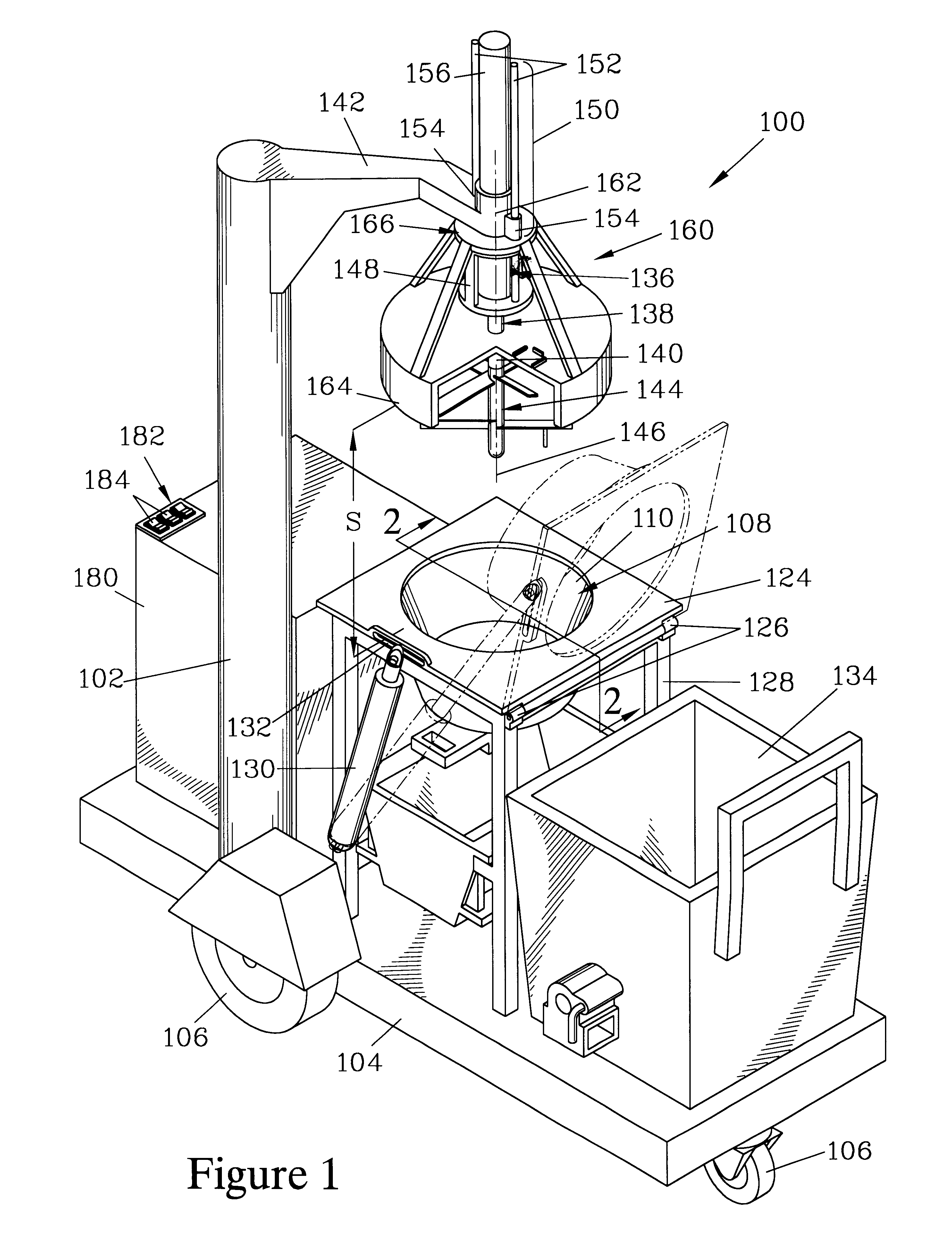
FIG. 1 is an isometric view of one embodiment of an improved dross processing system of the present invention. The dross processing system has a hood which serves to reduce radiation losses from the dross and to retain smoke and fumes generated by the dross as it is being processed in a reaction vessel. In FIG. 1, the hood is in a raised position and in a spacedapart relationship to the reaction vessel. The system as illustrated is provided with a housing containing a control system. A user interface has a series of switches allowing a user to activate various aspects of the dross processing procedure. The system also includes a spent dross container which is supported on a platform.

Problems solved by technology

While the apparatus of the '314 application can greatly facilitate recovery of metal from drosses, the apparatus has some limitations.
Employing such a structure to position the motor can limit the degree of control over vertical position of the motor and the impeller, and can result in gyrations of the impeller when it encounters irregularities in the dross.
These gyrations can result in damage of the impeller and / or the reaction vessel.
Furthermore, the design of the shields of the '314application is such that they tend to a safety hazard as they are moved into position.
Another limitation is that the system of the '314 application is designed to be operated manually, and thus depends on the skill of the operator as well the operator's willingness to take the extra steps necessary to recover metal from the dross.

Method used


Image

  • Dross processing system
  • Dross processing system
  • Dross processing system

Examples


Embodiment Construction

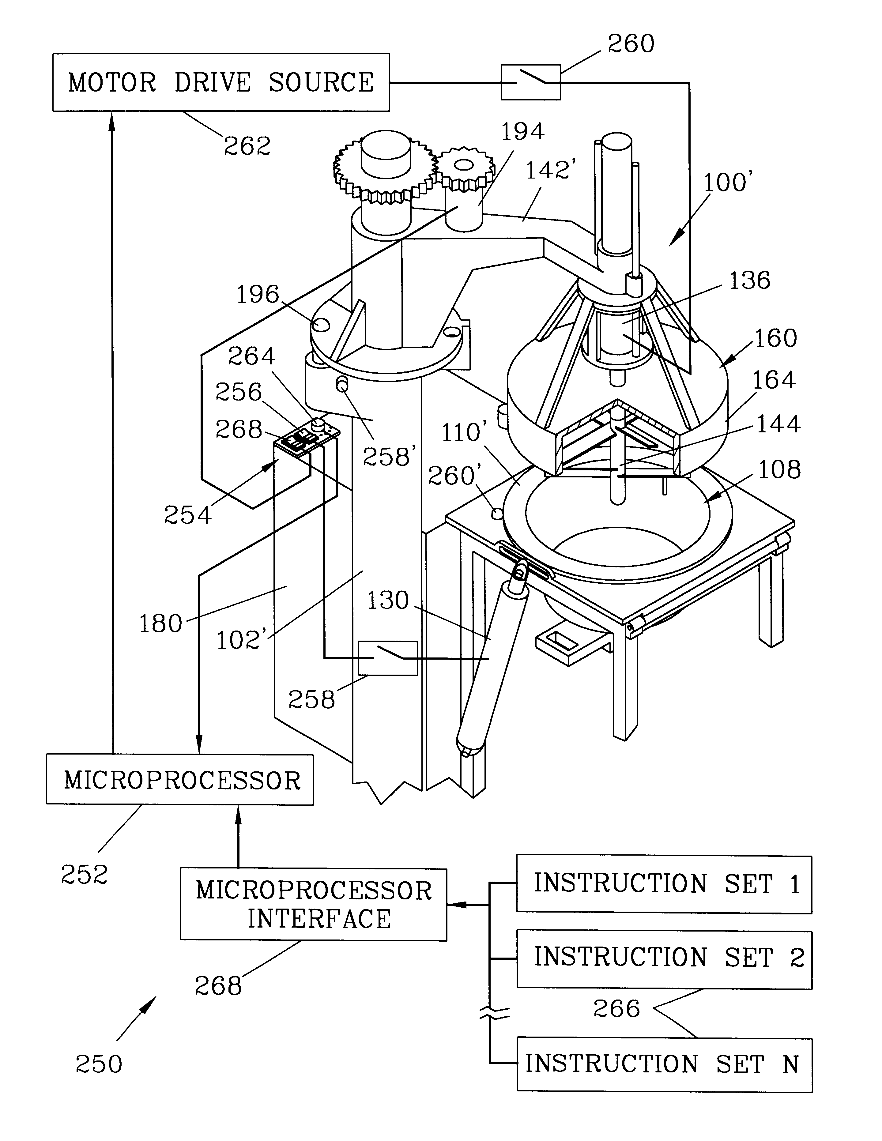
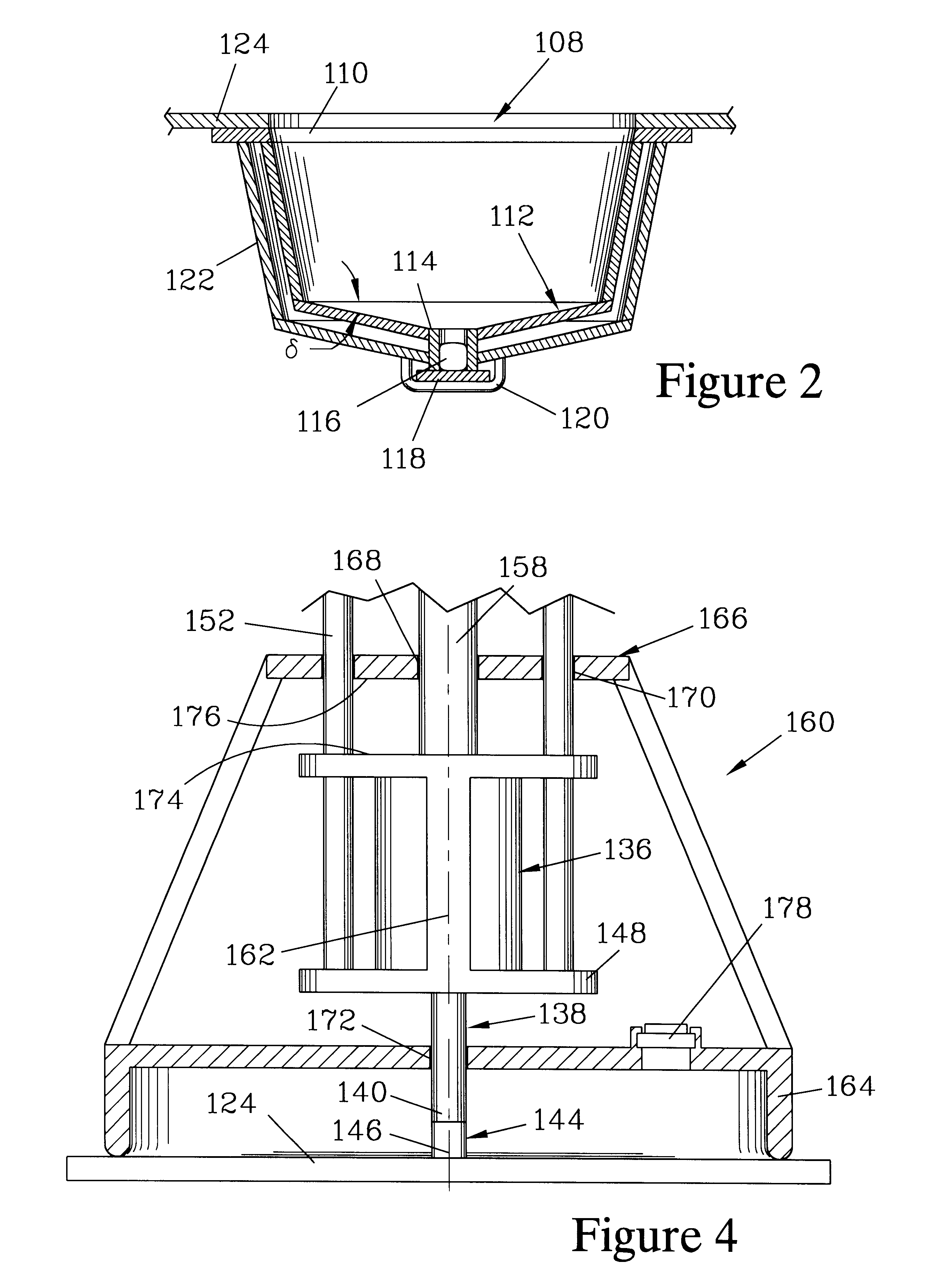
FIGS. 1 through 4 illustrate one embodiment of an improved dross processing system 100 of the present invention. FIGS. 1 and 3 are isometric views of the improved dross processing system 100, while FIG. 2 is a partial view of the section 2--2 of FIG. 1 illustrating details of a preferred reaction vessel employed in the present invention and FIG. 4 is a view of the section 4--4 of FIG. 3. Referring first to FIGS. 1 and 3, the dross processing system 100 has a substantially vertical support 102 which, in this embodiment, is mounted on a platform 104, which in turn is mounted on wheels 106 which allow the dross processing system 100 to be readily placed in close proximity to a furnace (not shown) from which dross is to be removed.

The dross processing system 100 is also provided with a reaction vessel 108 which holds the dross to be processed. Preferably, the reaction vessel 108 is a metal double-wall vessel such as described in U.S. patent application Ser No. 09 / 654,314 now U.S. Pat. N...


PUM

PropertyMeasurementUnit
timeaaaaaaaaaa
reaction forcesaaaaaaaaaa
depthsaaaaaaaaaa

Abstract

A dross processing system has a motor mounted to a motor support arm by a motor support carriage, and has a carriage guide which engages the motor support carriage to guide the motor along a vertical path between a raised position and a lowered position. The motor is moved by a motor height actuator connected between the motor support arm and the motor support carriage. A hood having a hood rim and a hood upper structure is configured to be engaged by the motor support carriage when moved to the raised position. When the motor is moved to the lowered position, the hood rim engages a reaction vessel upper rim. The motor support arm can rotate between a loading / dumping position and an operating position. The dross processing system can be partially automated by a microprocessor. A preferred impeller for agitating dross and a plug setting tool can be employed.

Description

To recover entrapped metal from drosses formed on melting and holding furnaces, the dross is placed in a reaction vessel and an exothermic flux is added to the dross. The dross is frequently agitated to promote coalescence of metal droplets therein. A molten metal pool forms in the bottom of the reaction vessel as the droplets coalesce. The molten metal pool is removed by draining through a bottom port. The demetallized or spent dross is then removed from the reaction vessel.One preferred apparatus for recovering metal employing such a method is described in U.S. patent application Ser No. 09 / 654,314, now U.S. Pat. No. 6,464,929 for which one of the present inventors is the inventor. While the apparatus of the '314 application can greatly facilitate recovery of metal from drosses, the apparatus has some limitations.The apparatus of the '314 application employs a motor to drive an impeller to agitate the dross while it is held in the reaction vessel. This apparatus, in some embodimen...

Claims


Application Information

Patent Timeline
Patent Type & Authority Patents(United States)
IPC IPC(8): C22B9/00C22B9/10C22B7/00C22B7/04C21B3/00C21B3/04
CPCC21B3/04C22B9/106C22B7/04C22B7/004Y02P10/20Y02W30/50
Inventor GROTEKE, DANIEL E.BECHER, EARL J.JUDKINS, TIMOTHY J.JUDKINS, JOSEPH A.
Owner Q C DESIGNS
Learn More