Separate mount ignition coil utilizing a progressive wound secondary winding

a secondary winding and separate mount technology, applied in the direction of transformers/inductance coils/windings/connections, inductances with magnetic cores, etc., can solve the problems of relatively difficult filling of the crossover region of the secondary winding spool with conventionally employed dielectric materials, and drawbacks of the segmented secondary winding configuration

Inactive Publication Date: 2003-04-29
DELPHI TECH INC
View PDF8 Cites 59 Cited by
  • Summary
  • Abstract
  • Description
  • Claims
  • Application Information

AI Technical Summary

Benefits of technology

An ignition coil assembly in accordance with the present invention includes a progressive wound secondary winding that results in a smaller package than a comparable segment wound ignition coil assembly. The invention further eliminates failure modes associated with ignition coils of the type having a segment wound secondary winding. Moreover, due to significant reductions in size, certain components conventionally found on remotely-mounted ignition coils, such as so-called "pole pieces" can be eliminated, thus providing an ignition coil assembly that has fewer components, uses fewer materials, provides a simplified core structure, all at a lower cost, smaller size, and having a reduced weight compared to conventional designs.

Problems solved by technology

However, there are drawbacks to the segmented secondary winding configuration.
First, a so-called crossover region of the secondary winding spool (i.e., a region to allow the secondary winding to transition between winding slots) is relatively difficult to fill with conventionally employed dielectric materials, such as epoxy potting material.
This difficulty is worsened when polyester material is used.
The foregoing described failure to fill certain areas with epoxy potting material leads to certain failure modes due to the lack of the needed electrical insulation in the secondary circuit.
Another drawback with segmented wound secondary windings involves the crossover region itself, where certain stresses on the winding increase the likelihood of failure.
A third drawback is that the axially spaced ribs increase the size the ignition coil itself.
The pole pieces, however, increase the cost, size and weight of the ignition coil.
However, it is not always possible or desirable to mount an ignition coil directly to the spark plug.
Therefore, in many instances, the coil must be mounted remotely, and therefore the teachings of Sakamaki et al. cannot be followed.

Method used


Image

  • Separate mount ignition coil utilizing a progressive wound secondary winding
  • Separate mount ignition coil utilizing a progressive wound secondary winding
  • Separate mount ignition coil utilizing a progressive wound secondary winding

Examples


Embodiment Construction

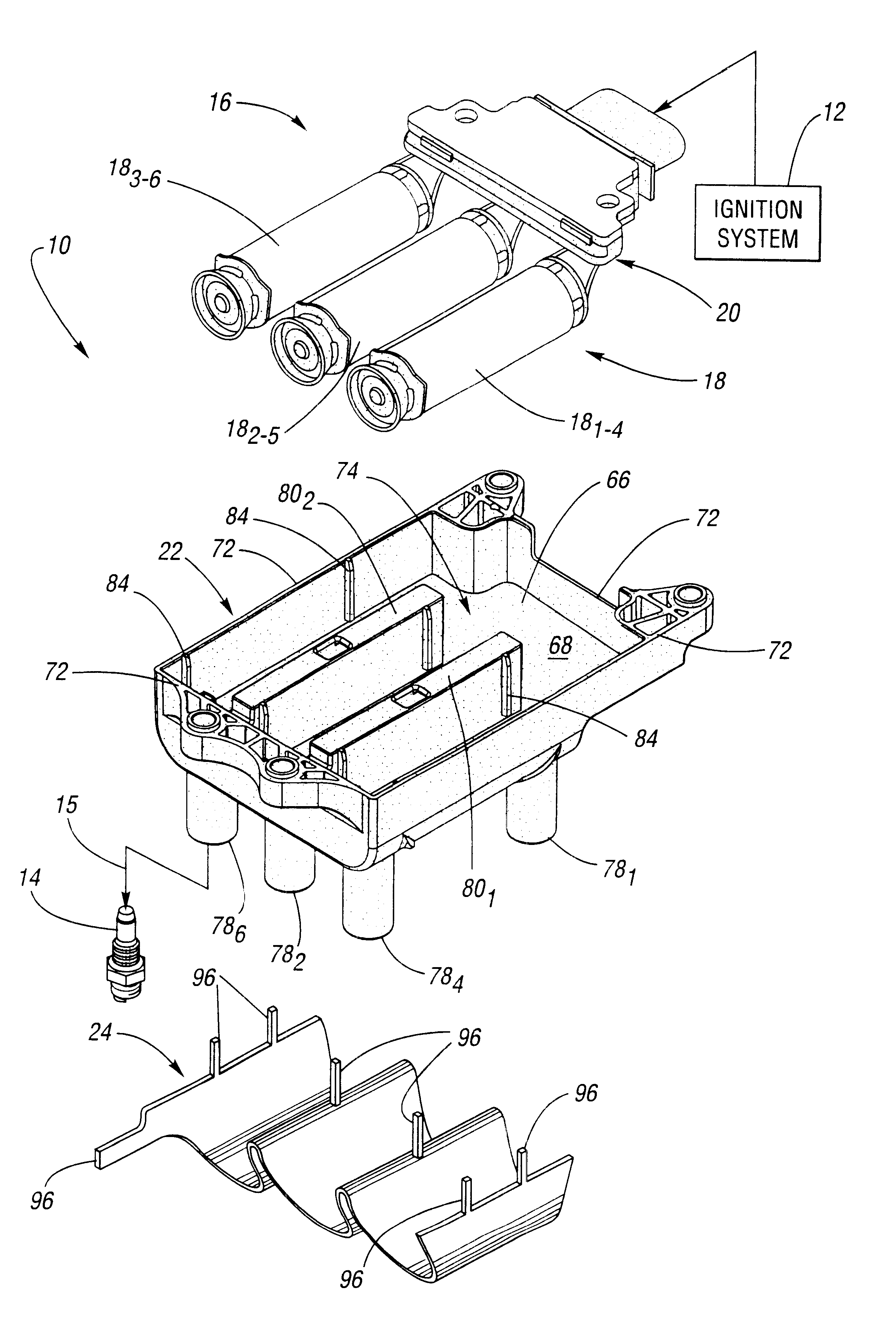
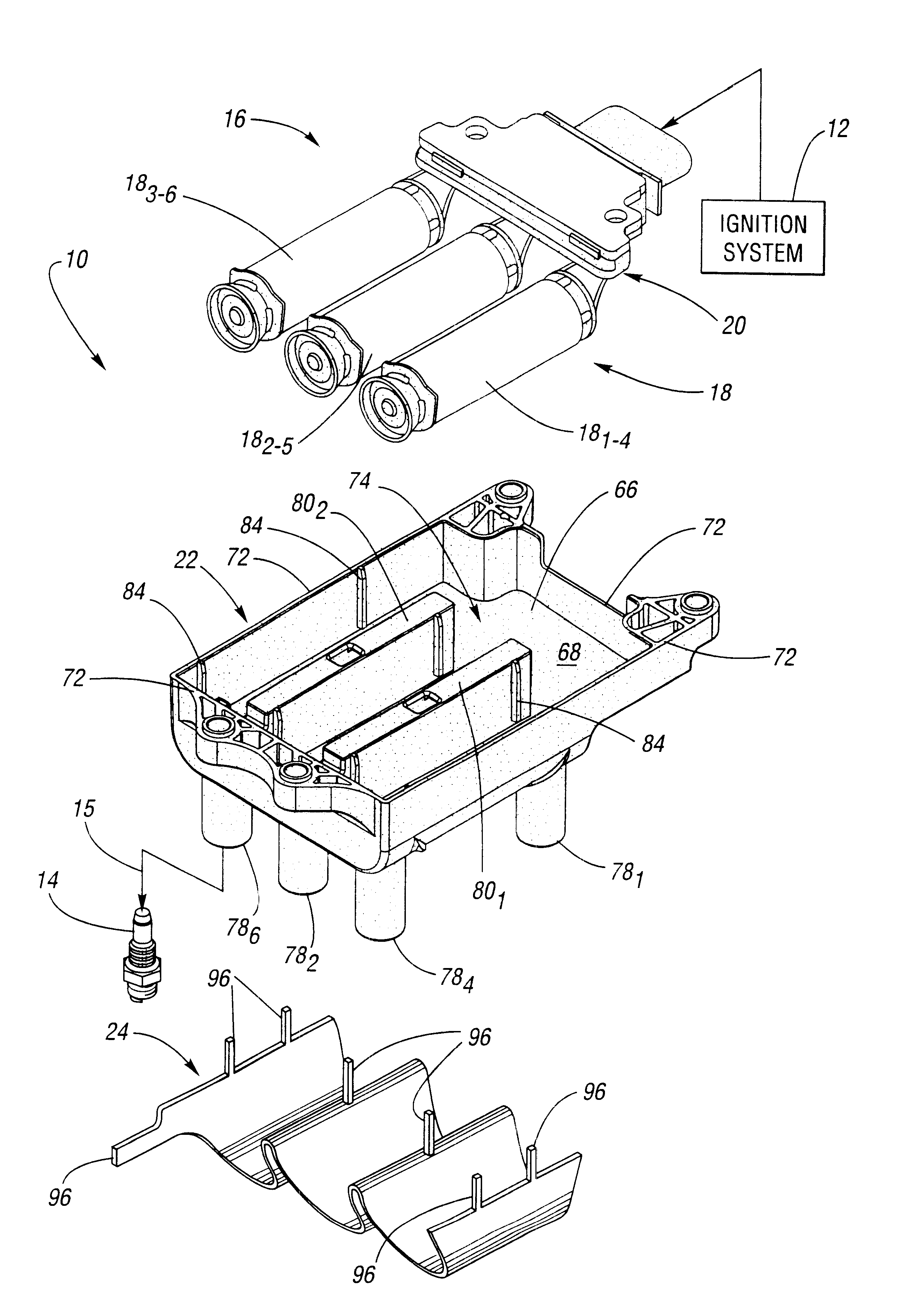
Referring now to the drawings wherein like reference numerals are used to identify identical components in the various views, FIG. 1 is an exploded, perspective view of an ignition coil assembly 10 in accordance with the present invention. As is generally known, ignition coil assembly 10 may be coupled to, for example, an ignition system 12, which contains primary energization circuitry for controlling the charging and discharging of ignition coil assembly 10. Further, also as is well known, the relatively high-voltage produced by ignition coil assembly 10 is provided to a conventional spark plug 14 remotely mounted from ignition coil assembly 10 by way of a conventional ignition cable 15. Spark plug 14 may be retained by a threaded engagement with a spark plug opening in a combustion chamber of the engine (as conventional). The resulting spark event may be employed to initiate combustion in a combustion chamber of an internal combustion engine. Such an engine (not shown) may be use...


PUM

PropertyMeasurementUnit
voltageaaaaaaaaaa
current Ipaaaaaaaaaa
resistanceaaaaaaaaaa

Abstract

An ignition coil assembly includes a core formed of magnetically-permeable material extending along a main axis, a primary winding disposed about the core, a secondary winding disposed on a secondary winding spool wherein at least one of the secondary winding leads is connected to a high-voltage connector terminal portion of the ignition coil assembly configured for connection to a remotely disposed spark plug, a case formed of electrical insulating material, and a magnetically-permeable shield disposed outwardly of the case. The secondary winding is progressively wound on the secondary winding spool, thereby eliminating failure modes associated with the segment-wound secondary windings, and, eliminating the need for pole pieces in the magnetic circuit, thereby reducing components, cost, weight, and size of the ignition coil assembly.

Description

1. Field of the InventionThe present invention relates generally to ignition coils for developing a spark firing voltage that is applied to one or more remotely mounted spark plugs of an internal combustion engine.2. Description of the Related ArtAn ignition coil configured to be mounted in an automotive engine compartment remotely from a spark plug is known that includes a so-called "segment" wound secondary winding, as seen by reference to U.S. Pat. No. 5,015,982 issued to Skinner et al. Skinner et al. disclose an ignition coil configured for operation in a waste spark system having a magnetically-permeable core, a primary winding, and a secondary winding disposed on a secondary winding spool. The first and second ends of the secondary winding are connected to respective high-voltage towers for connection to remotely installed spark plugs. The secondary winding spool disclosed in Skinner et al. further includes a plurality of axially spaced and circumferentially extending ribs, wh...

Claims


Application Information

Patent Timeline
Patent Type & Authority Patents(United States)
IPC IPC(8): F02P3/02H01F38/00H01F38/12
CPCH01F38/12F02P3/02
Inventor SKINNER, ALBERT ANTHONY
Owner DELPHI TECH INC
Why Eureka
Try Eureka