Synthetic aperture ladar system using incoherent laser pulses

a laser pulse and incoherent technology, applied in the field of laser radar systems, can solve the problems of difficult or impossible implementation of certain types of noise filtering, affecting the performance of systems, and unable to perform noise filtering

Inactive Publication Date: 2003-05-06
RAYTHEON CO
View PDF7 Cites 60 Cited by
  • Summary
  • Abstract
  • Description
  • Claims
  • Application Information

AI Technical Summary

Problems solved by technology

Conventional noncoherent ladar systems typically lack phase and frequency information pertaining to the transmitted laser beam.
Consequently, without laser spectrum information, certain types of noise filtering, which would increase SNR, are difficult or impossible to implement.
Noncoherent ladar systems generally do not perform this noise filtering, since they lack requisite spectrum information pertaining to the transmitted laser beam.
Unfortunately, coherent ladar systems are generally more sensitive to misalignments and beam distortions.
In a conventional ladar imaging system not employing synthetic aperture methods, image cross-resolution is limited by the size of the ladar system aperture.
Very large and expensive apertures are required to obtain sufficient resolution for many current long-range imaging and mapping applications.
This is particularly problematic for ladar systems employed in satellites or missile systems, which have prohibitive space constraints and require long-range viewing capabilities.
High resolution topography applications operating at a range of approximately 100 kilometers, an eye-safe laser wavelength of 1.5.times.10.sup.-6 m, and a typical cross resolution of 20 cm, require a conventional aperture of approximately 75 cm, which is prohibitively large and expensive for many applications.
The large apertures are also undesirably sensitive to thermal and gravitational distortions.
Typically, coherent waveforms longer than a fraction of a millisecond are difficult to achieve, especially at high power levels.
Consequently, conventional synthetic aperture ladar systems have generally been unsuccessful in achieving this bandwidth time product.
Previous synthetic aperture ladar systems could not maintain transmitter coherence for sufficient duration to accurately measure a scene.
Accurate synthetic aperture measurements require relatively high beam pulse energy for which coherence is difficult to maintain.
Unfortunately, these systems have difficulty maintaining laser beam coherence, yielding inferior imaging capabilities.
This severely limits waveform selection, preventing use of otherwise more desirable waveforms, such as high-energy Q-switched pulses.

Method used


Image

  • Synthetic aperture ladar system using incoherent laser pulses
  • Synthetic aperture ladar system using incoherent laser pulses
  • Synthetic aperture ladar system using incoherent laser pulses

Examples


Embodiment Construction

While the present invention is described herein with reference to illustrative embodiments for particular applications, it should be understood that the invention is not limited thereto. Those having ordinary skill in the art and access to the teachings provided herein will recognize additional modifications, applications, and embodiments within the scope thereof and additional fields in which the present invention would be of significant utility.

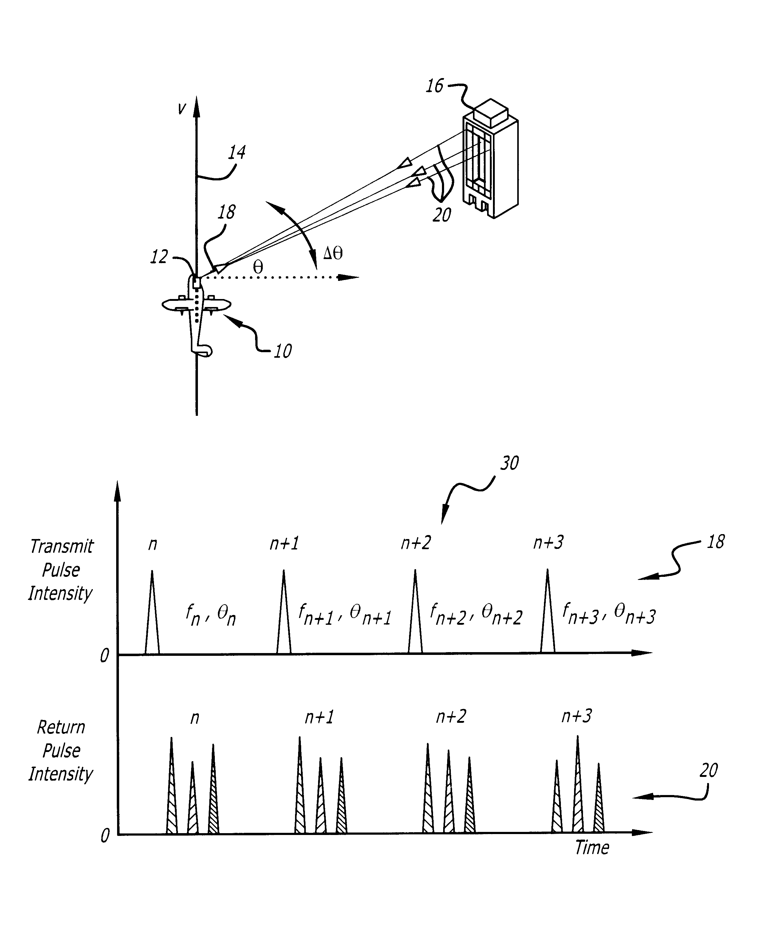
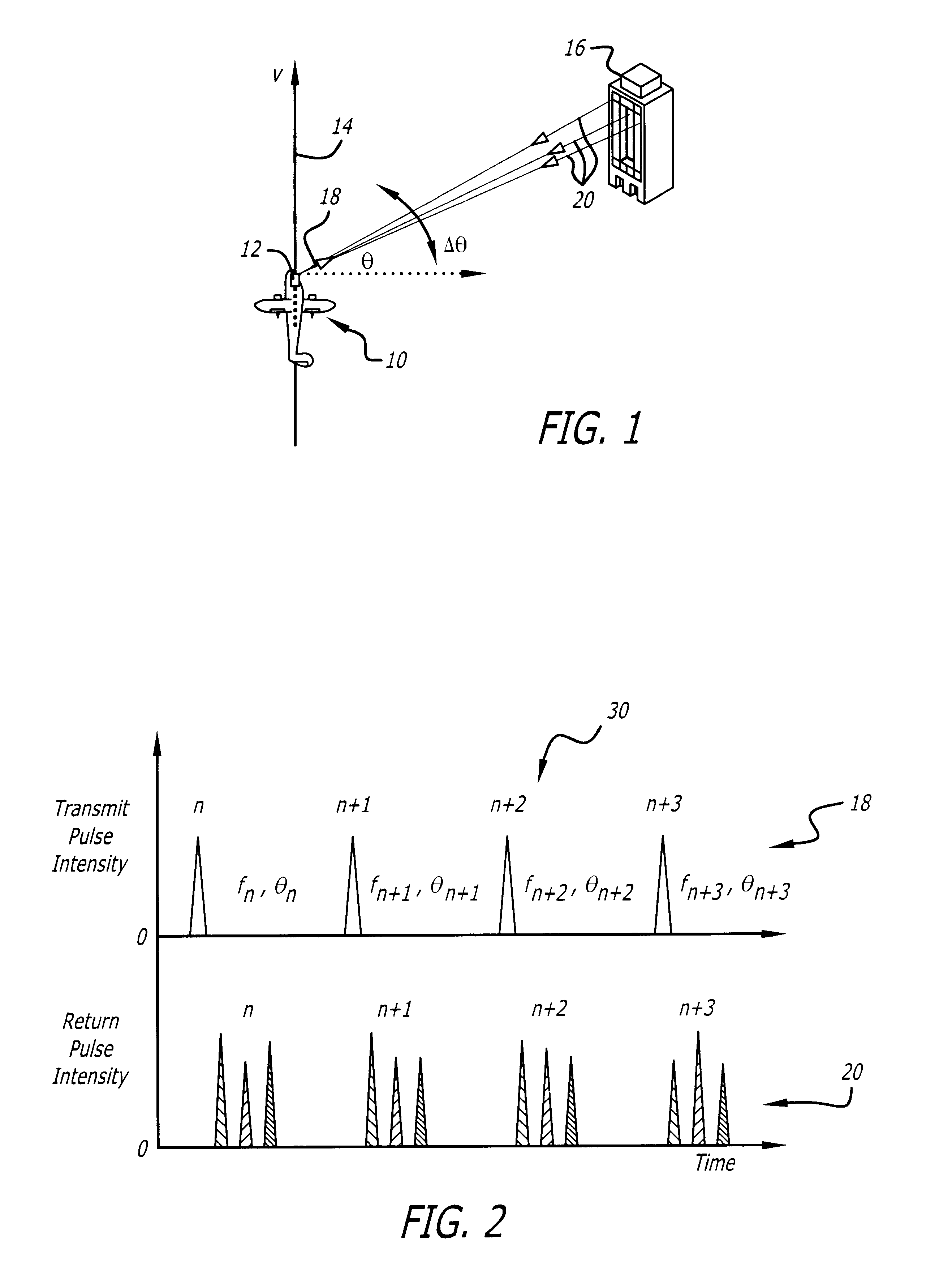
FIG. 1 is a diagram showing an aircraft 10 employing a ladar system 12 constructed in accordance with the teachings of the present invention and illustrating general ladar principles of operation. The aircraft 10 has a velocity vector (V) 14 as it flies by a building 16. The ladar system 12 is mounted on the front of the aircraft 10 and transmits a laser beam 18 toward the building 16.

In the present embodiment, the transmitted laser beam 18 is a high-energy eye-safe Q-switched pulsed laser beam comprising a sequence of high-energy pulses. T...


PUM


Abstract

An incoherent ladar transmitter (12) adapted for use with synthetic aperture processing. The system (12) includes a first mechanism (44, 48, 50) for generating a laser beam (18). A second mechanism (44, 68) records phase information pertaining to the laser beam (18) and subsequently transmits the laser beam (18) from the system in response thereto. A third mechanism (40) receives a reflected version (20) of the laser beam and provides a received signal in response thereto. A fourth mechanism (72) corrects the received signal based on the phase information recorded by the second mechanism (44, 68). In a more specific embodiment, the ladar system (12) includes a synthetic aperture processor (46) for correcting the received signal based on the phase information and providing a corrected laser signal in response thereto. The synthetic aperture processor (46) includes a mechanism (76) for applying, a Discrete Fourier Transform (DFT) to the corrected laser signal to obtain high frequency resolution and cross-range resolution. A fifth mechanism (48) constructs a range-Doppler image based on the corrected laser signal and the movement of the ladar system (12).

Description

1. Field of InventionThis invention relates to laser radar systems (ladars). Specifically, the present invention relates to synthetic aperture ladar systems employing incoherent laser pulses.2. Description of the Related ArtLadar systems are employed in various applications including high-resolution 3-dimensional imaging, mapping, chemical analysis, and military targeting applications. Such applications require accurate, space-efficient, and cost-effective ladar systems.Ladar systems are particularly applicable for long-range, high-resolution 3-dimensional imaging applications employed in terrain mapping and target imaging applications on satellites and missile systems. A ladar system often includes a sensor suite mounted on a satellite, missile system, or aircraft. The sensor suite has one or more fixed physical apertures through which a ladar system views a scene. A ladar system views a scene by transmitting a laser through the aperture toward the scene. The laser reflects off the...

Claims


Application Information

Patent Timeline
Patent Type & Authority Patents(United States)
IPC IPC(8): G01S17/10G01S17/00G01S17/50G01S17/89G01S17/90G01S17/18
CPCG01S17/107G01S17/895G01S17/50G01S17/90G01S17/18
Inventor HALMOS, MAURICE J.
Owner RAYTHEON CO
Why Eureka
Try Eureka