Method and circuit arrangement for reducing noise produced by electromagnetically actuated devices

a technology of electromagnetic actuation and circuit arrangement, which is applied in the direction of machines/engines, non-mechanical valves, magnetic bodies, etc., can solve the problems of noise and wear, excessive acceleration and drive of armatures, and excessive transfer and conversion of energy

Inactive Publication Date: 2003-05-06
DAIMLER AG
View PDF19 Cites 53 Cited by
  • Summary
  • Abstract
  • Description
  • Claims
  • Application Information

AI Technical Summary

Problems solved by technology

As a result, the armature is very strongly and excessively accelerated and driven against a mechanical end limit stop or the like.
The rapid excessive acceleration of the armature, and especially the impact of the excessively accelerated armature against its mechanical end limit stop results in the transfer and conversion of excessive amounts of energy.
The greater the actuating current that is applied to the magnetic coil, the greater will be the acceleration and the ultimate velocity and energy of the armature, and thus also the greater will be the amount of noise and wear produced when the armature impacts against the end limit stop.
A disadvantage of such a known approach is that the specific time point of actuation of the armature is not specifically controlled or defined.
Unfortunately, that leads to an actuation of the electromagnet at a higher current level than would be absolutely necessary, i.e. at a higher current than the abovementioned minimum threshold level, because the current keeps rapidly increasing even as the armature is being actuated.
As a result, the armature is excessively accelerated, and caused to strongly impact against the mechanical stop, which leads to a higher generation of noise and also increased wear of the various mechanical components.
Particularly, the current increase during each of the non-actuating ranges may be a substantially instantaneous current jump, limited only by the inherent inductance and available driving voltage of the circuit.
On the other hand, during the initial and final non-actuating ranges, the semiconductor switching element does not apply a significant resistance, so that the current can increase in a substantial jump manner in a very short time interval (limited by the available voltage and the inductivity of the circuit), so that only a small amount of heat is generated in the semiconductor switching element during operation in these ranges.

Method used


Image

  • Method and circuit arrangement for reducing noise produced by electromagnetically actuated devices
  • Method and circuit arrangement for reducing noise produced by electromagnetically actuated devices
  • Method and circuit arrangement for reducing noise produced by electromagnetically actuated devices

Examples


Embodiment Construction

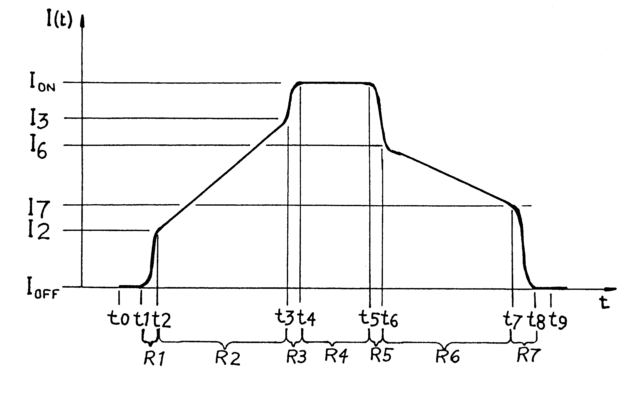
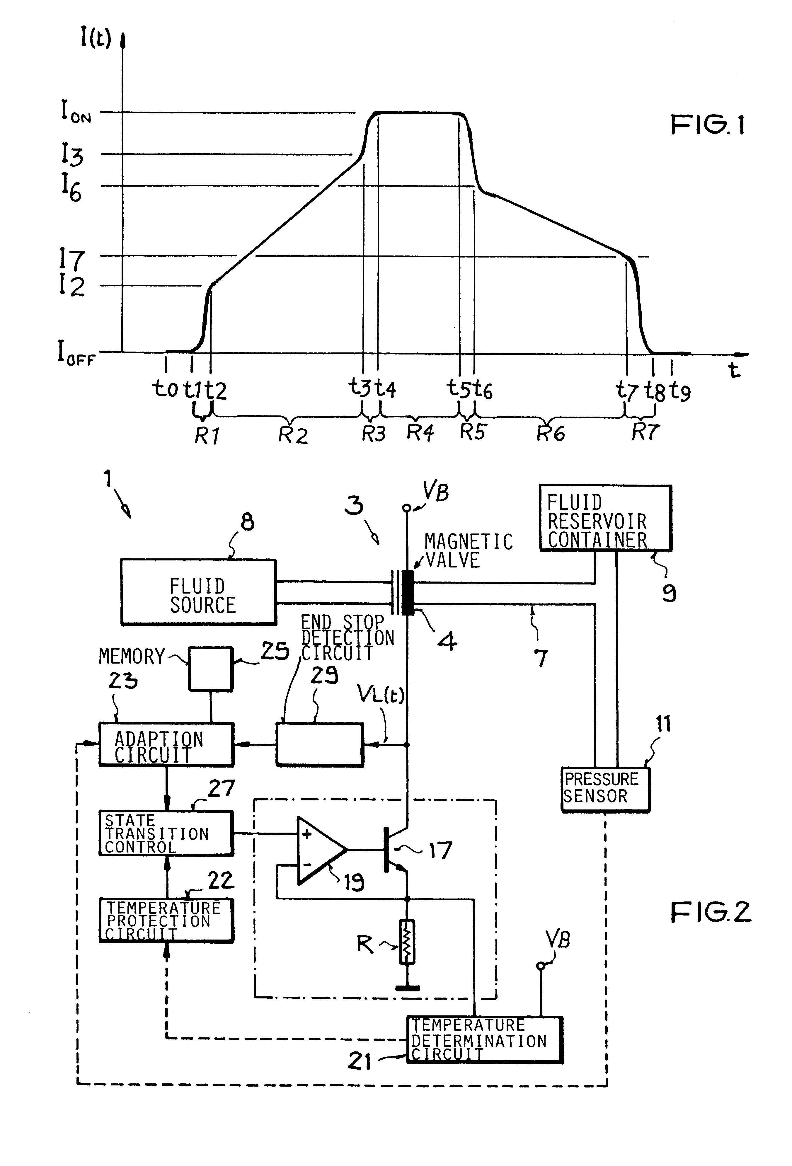
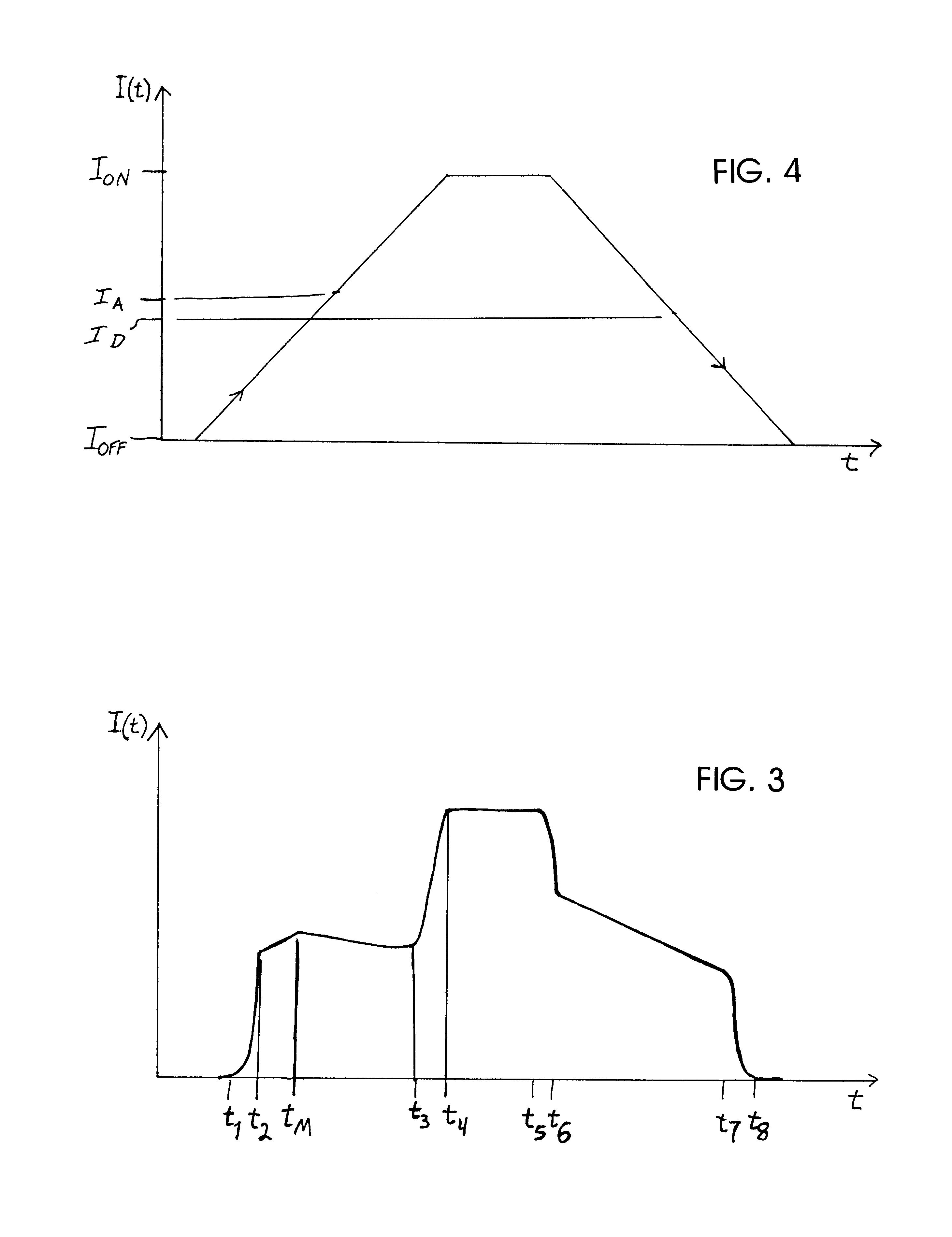
FIG. 1 schematically shows the time progression of the current that is supplied to and flows through the magnetic coil of an electromagnet of an electromagnetically switch able device such as a relay or a magnetically operable valve. The diagram extends over the operating time of a complete cycle in which the electromagnet is initially at rest, i.e. not actuated, at a time t.sub.0, the electromagnet is then switched to an activated state between time t.sub.1 and t.sub.4, the electromagnet remains in the actuated state from time t.sub.4 to t.sub.5, and then the electromagnet is switched to a deactivated state between times t.sub.5 and t.sub.8 and then remains deactivated at time t.sub.9.

During this cycle, the current applied to the electromagnet varies between a minimum or "off" current, e.g. zero amps, designated by I.sub.OFF, and a maximum actuated current designated by I.sub.ON. The increasing of the applied current from the minimum value I.sub.OFF to the maximum value I.sub.ON ta...


PUM

PropertyMeasurementUnit
electrical actuating currentaaaaaaaaaa
timeaaaaaaaaaa
current increasing rateaaaaaaaaaa

Abstract

In an electromagnetically actuatable device, an electromagnet is driven with a controlled current progression so that the armature of the electromagnet can be actuated at the lowest possible current level while still achieving the most rapid overall increase of the actuating current from zero to maximum amperage. A first portion or range of the current increase is carried out with a steep or jump-like current increasing characteristic. A second portion or range of the current increase is carried out with a more gradual variation of the current. The current levels at the end points of the respective ranges are selected to ensure that the electromagnet is actuated during the second range in which the current varies more gradually. Preferably, two steep or jump-like current increase ranges are respectively provided before and after the second range having the gradual current increase. The armature of the electromagnet is thereby actuated with the lowest possible energy, and the lowest possible acceleration, so that noise and wear are reduced.

Description

PRIORITY CLAIMThis application is based on and claims the priority under 35 U.S.C. .sctn.119 of German Patent Application 198 60 272.3, filed on Dec. 24, 1998 the entire disclosure of which is incorporated herein by reference.The invention relates to a method and a circuit arrangement for reducing the level of noise produced during actuation of an electromagnetically actuated device, whereby such noise results from excessive acceleration and deceleration of an armature of the device when an excessive actuating current has been applied to the device.BACKGROUND INFORMATIONVarious types of electromagnetically actuated or operated devices, such as electromagnetic valves and relays for example, are known in the art. Such devices typically comprise an electromagnet including a magnetic coil as well as a movable armature, which is moved or changed in position when a sufficient actuating current is applied to the magnetic coil. More particularly, the armature begins to move once the actuati...

Claims


Application Information

Patent Timeline
Patent Type & Authority Patents(United States)
IPC IPC(8): F01L9/04H01F7/18H01F7/08F01L9/20
CPCF01L9/04H01F7/18H01F2007/1894F01L2201/00F01L9/20
Inventor BECK, STEFANEBEL, MARTINPOEPPEL, JOSEF
Owner DAIMLER AG
Why Eureka
Try Eureka