Machining apparatus

a technology of machining instruments and machining parts, which is applied in the field of machining instruments, can solve the problems of occupying much needed space in the instrument, affecting the design of such equipment, and reducing the use of machining instruments

Inactive Publication Date: 2003-05-13
COMPANION SPINE LLC +1
View PDF165 Cites 65 Cited by
  • Summary
  • Abstract
  • Description
  • Claims
  • Application Information

AI Technical Summary

Problems solved by technology

In some of these procedures, the human anatomy provides little room to maneuver and properly position a machining instrument.
These difficulties, caused at least in part by the environment in which the machining instrument is used, create significant design constraints.
At the same time, the device may require translational gears to provide the necessary angled machining, which take up much needed space in the instrument.
The tension between these conflicting requirements often results in significant design tradeoffs for such equipment.
These forces may be relatively significant, particularly in view of the size limitations of the components.
Excessive heat generation will result in unwanted damage to the living hard tissue and other surrounding tissues in the form of thermal necrosis.
In particular, when machining bony tissue, excessive heat can kill osteoblasts in the vicinity of the machining operation, which can lengthen healing times and limit desired bony ingrowth into devices implanted into cavities formed by the machining device.
Such space constraints are often met by the use of high gear ratios, resulting in suboptimal pinion teeth geometry.
The resulting wear significantly limits the life span of such surgical instruments.
In addition, these types of machining instruments are repeatedly exposed to harsh environments that can also shorten their useful life.
Specifically, these instruments are often subjected to repeated heat cycles and corrosive cleaning agents during sterilization or autoclaving prior to each use.
Therefore, the materials used to fabricate the machining instruments must be biocompatible and capable of withstanding the extreme sterilization temperatures that typically exceed 135.degree. C.
In addition, the repeated thermal expansion and contraction of the materials may result in a degradation of some of the mechanical interfaces in the device.
The '228 Patent disclosures does not provide any details on how the device disclosed therein is constructed, and does not address the issues outlined above.
Although this design is effective to machine a vertebral body endplate, the inventors of this application have discovered that, over time, the usefulness of the device may become less reliable.
In particular, the repeated use of the device may result in failure of the outer gear ring 10 as a result of the stresses exerted by the press fit of axial hub 12 and / or loads applied during use.
In addition, the repeated sterilization of the device may compromise the effectiveness of the adhesives used to secure bearing assembly 6 to the housing.

Method used


Image

  • Machining apparatus
  • Machining apparatus
  • Machining apparatus

Examples


Embodiment Construction

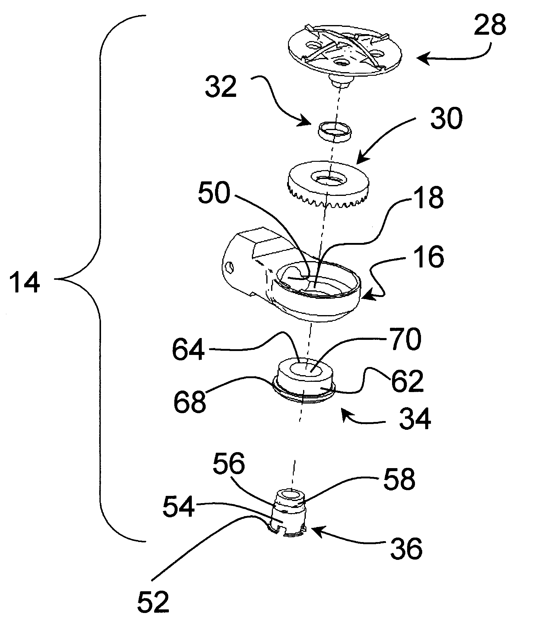
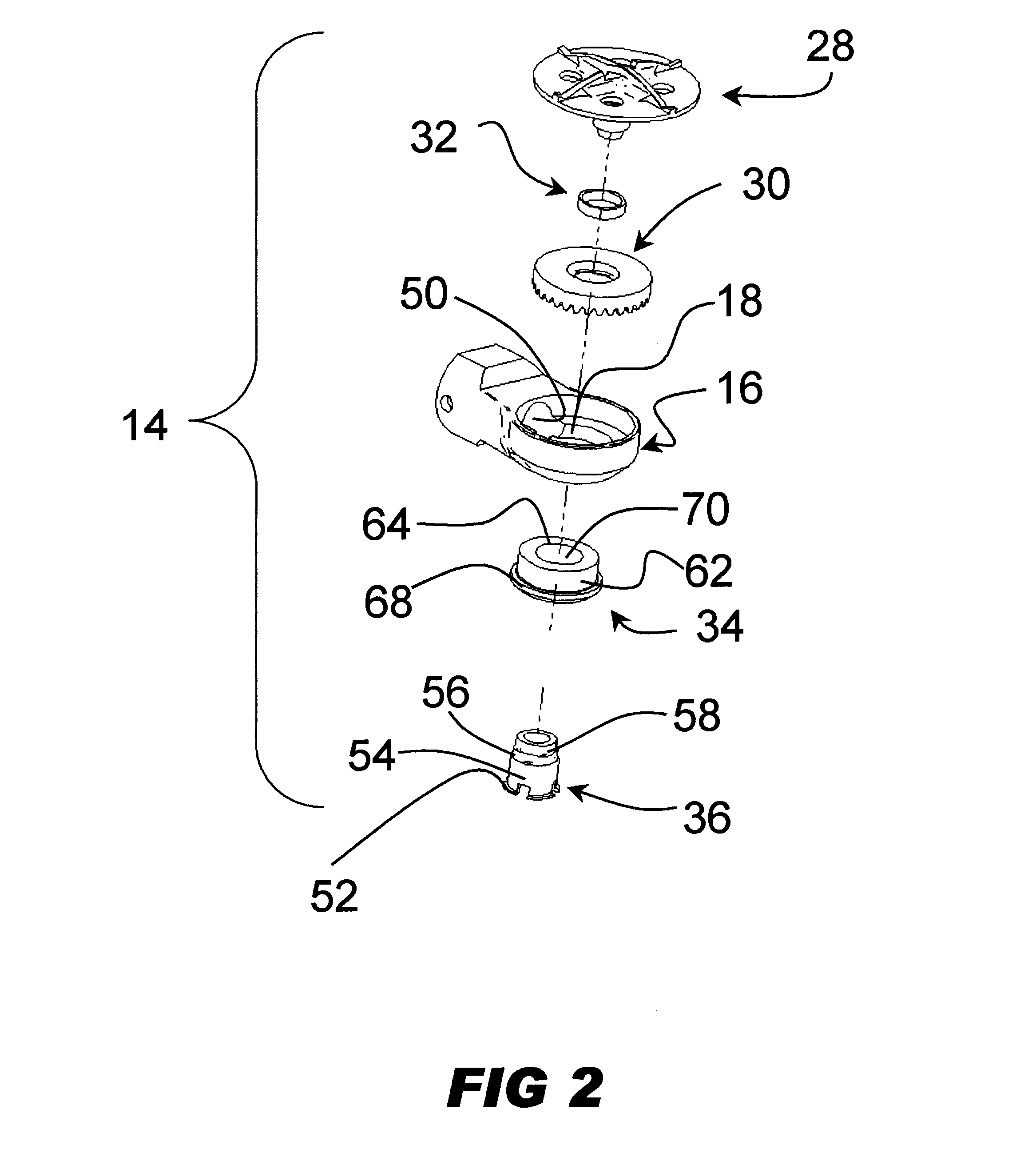
In general, the present invention provides an apparatus for removing material from the surface of tissue, including hard tissue, such as bone. Preferably, the apparatus is used to form a cavity in a bone surface through a machining process.

The apparatus includes a drive mechanism including a gear, a bearing assembly and a gear hub positioned within a housing, and a cavity forming member mounted on the mounting structure. Preferably the cavity forming member is a machining element, and more preferably it is a bone cutting element. The apparatus includes first means for securing the gear, bearing assembly and gear hub together to form the drive mechanism within an opening in the housing, and second means for securing the machining element to the drive mechanism. In accordance with an embodiment of the present invention, the first means includes a first locking member adjacent the gear and a second locking member adjacent the hub. The first and second locking members provide opposing f...


PUM


Abstract

The invention relates to an apparatus for machining hard tissue and soft tissue associated therewith, having a housing, a rotating shaft having an axis essentially parallel to a longitudinal axis of the apparatus, and adapted to provide power to the apparatus by rotation of the shaft, a drive assembly, having a gear having a rotational axis oriented perpendicular to the longitudinal axis of the apparatus and adapted to mesh with the rotating shaft, a gear hub rigidly attached to the gear, which rotates when the gear rotates, and adapted to attached to a bearing assembly, a bearing assembly having a moveable member rigidly attached to the gear hub, a non-moveable member rigidly attached to the housing, and one or more friction reducing members disposed between the moveable and non-moveable members, and two or more locking members adapted to generate opposing forces helping to hold the drive assembly together, and a cutting element rigidly attached to the drive assembly, wherein the gear hub and bearing assembly are press fit together and the gear and gear hub each comprise complementary interlocking noncircular geometries.

Description

1. Field of the InventionThis invention relates generally to machining instruments, and in particular to surgical instruments that are capable of machining hard tissues in relatively confined or constrained environments or spaces, and yet remain reliable for extended periods.2. Description of Related ArtIn a variety of surgical procedures there is a need to machine hard tissues such as bone, i.e. cut, abrade, obliterate or remove hard tissue by mechanical means. In some of these procedures, the human anatomy provides little room to maneuver and properly position a machining instrument. Furthermore, in some procedures precise machining must be done at an angle relative to the direction at which the machining instrument is inserted. These difficulties, caused at least in part by the environment in which the machining instrument is used, create significant design constraints. For example, the components used to make the machining instrument must often be small so that the device can fi...

Claims


Application Information

Patent Timeline
Patent Type & Authority Patents(United States)
IPC IPC(8): A61B17/16A61B17/17A61B17/02A61B19/00A61B17/00A61B17/56
CPCA61B17/02A61B17/1671A61B17/1757A61B17/162A61B17/1624A61B17/1659A61B2019/304A61B19/20A61B19/26A61B2017/00867A61B2017/0256A61B2017/1602A61B90/10A61B90/50A61B2090/034
Inventor GIL, CARLOSTOKISH, LEN
Owner COMPANION SPINE LLC
Why Eureka
Try Eureka