
Solid electrolytic capacitor

a technology of solid electrolytic capacitors and capacitors, which is applied in the direction of electrolytic capacitors, capacitor electrodes, liquid electrolytic capacitors, etc., can solve the problems of insufficient effects and rough surface of a portion of lead in which the conductor is provided,

Inactive Publication Date: 2003-05-13
PANASONIC CORP
View PDF5 Cites 37 Cited by
  • Summary
  • Abstract
  • Description
  • Claims
  • Application Information

AI Technical Summary

Problems solved by technology

However, since the connection resistance is inversely proportional to the area of the connection surface, sufficient effects cannot be obtained simply by applying a plating process technique or a conductive adhesive that allows connection at a low resistance to a flat connection surface.
In this case, the surface of a portion of the lead in which the conductor is provided may be rough.

Method used


Image

  • Solid electrolytic capacitor
  • Solid electrolytic capacitor
  • Solid electrolytic capacitor

Examples


embodiment 1

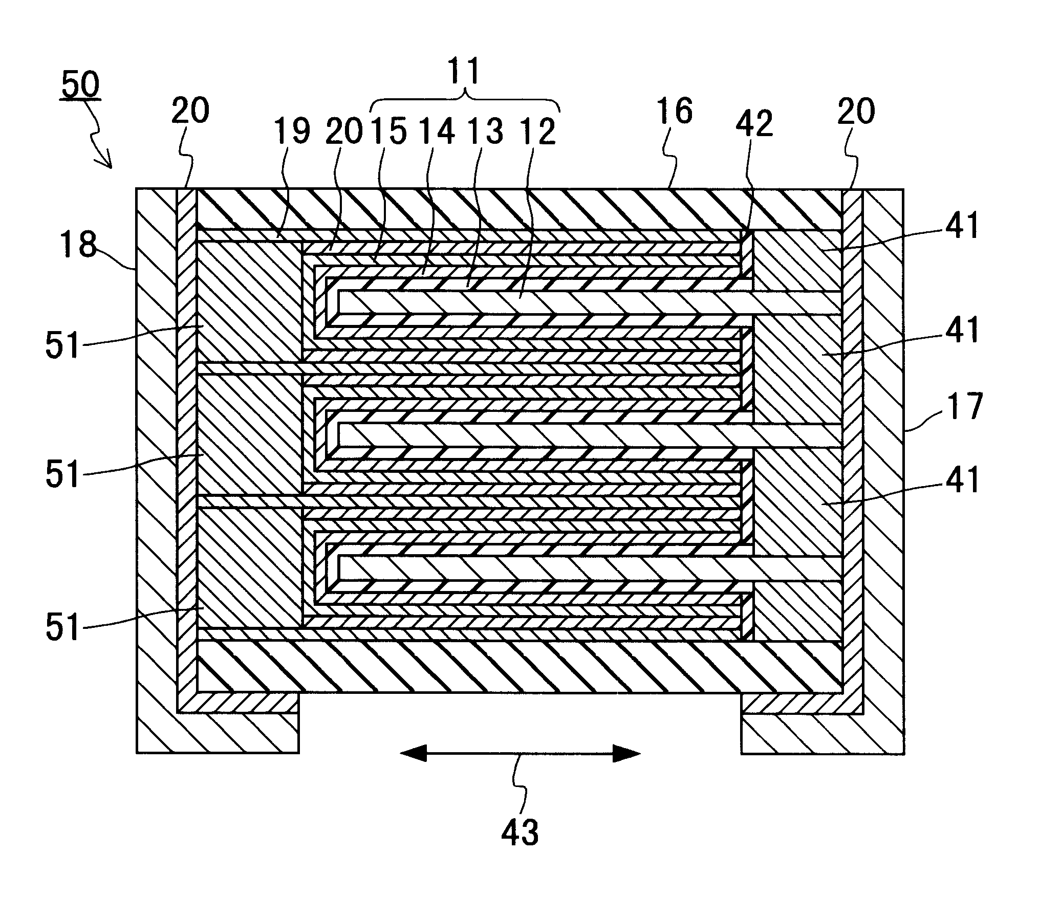
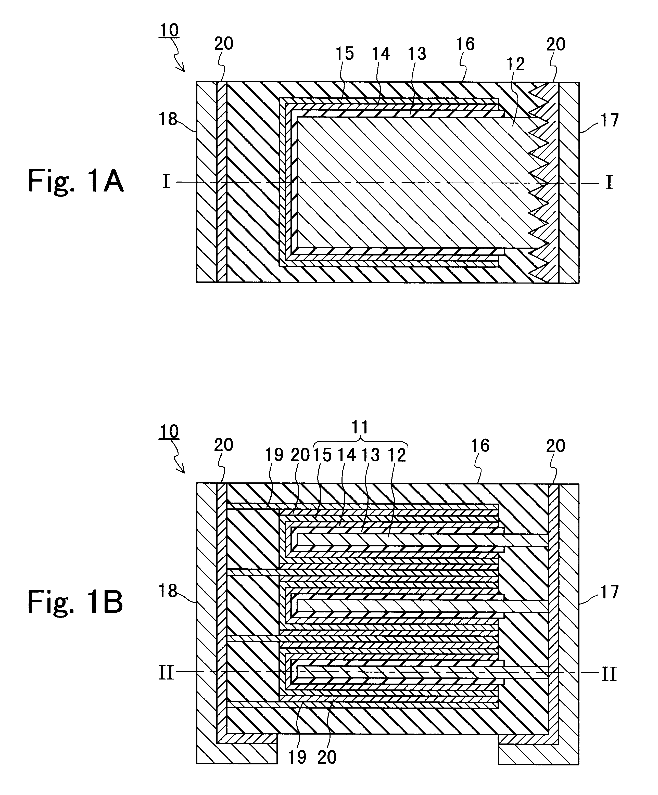
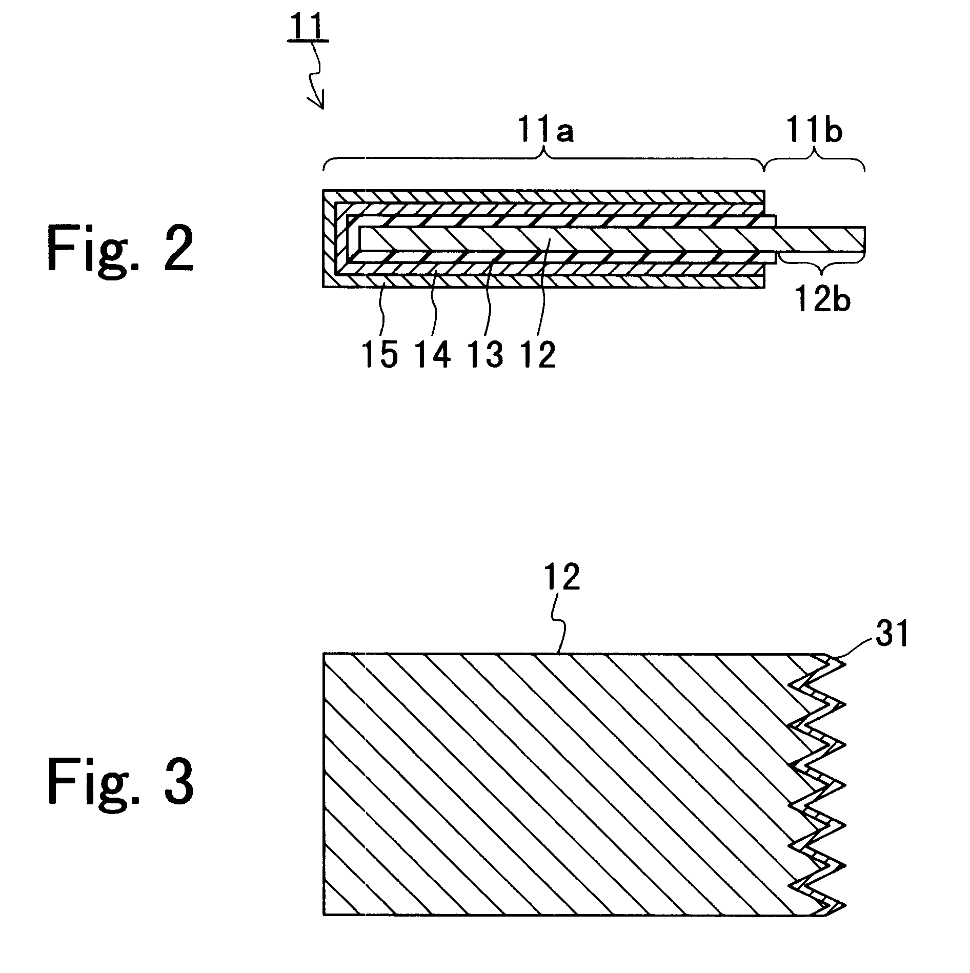
A lead frame was attached to the conductive layer of the capacitor element of the outermost layer of the laminate with a silver paste. Thereafter, the laminate was coated with an encapsulating resin by molding. Next, the molded laminate was cut at a predetermined position to expose the lead frame on the cathode side and the anode drawn-out portion of the anode. The exposed anode side was processed so as to be saw tooth shaped to increase the surface area. This process was performed with a cutting machine with an outer circumferential blade. Then, a zinc layer was formed on the surface of the exposed anode drawn-out portion by metal substitution. Thereafter, a nickel layer and a gold layer were formed in this order by electroless plating. Finally, an anode terminal was attached with a silver paste. Thus, a solid electrolytic capacitor (sample A) of produced.

On the other hand, a solid electrolytic capacitor (sample B) was produced in the same manner as in the case of sample A, except ...

embodiment 2

A lead frame was attached to the conductive layer of the outermost layer of the laminate with a silver paste. Thereafter, the laminate was coated with an encapsulating resin by molding. Next, the molded laminate was cut at a predetermined position to expose the lead frame on the cathode side, the anode drawn-out portion and the silver foil stacked on the anode drawn-out portion. The exposed side face on the anode side was processed so as to be saw tooth shaped to increase the surface area. Then, a zinc layer was formed on the surface of the exposed anode drawn-out portion by metal substitution. Thereafter, a nickel layer and a gold layer were formed in this order on the surfaces of the zinc layer and the exposed silver foil by electroless plating. Finally, an anode terminal was attached with a silver paste. Thus, a solid electrolytic capacitor (sample C) of produced.

On the other hand, a solid electrolytic capacitor (sample D) was produced in the same manner as in the case of sample ...


PUM


Abstract

A solid electrolytic capacitor includes a capacitor element including a capacitance forming portion; an encapsulating resin with which the capacitance forming portion is coated; an anode terminal and a cathode terminal that are provided such that at least a part thereof is outside the encapsulating resin; and a lead. The capacitor element includes an anode, and a dielectric layer and a solid electrolytic layer that are laminated on a portion of the anode in this order. The lead is electrically connected to the solid electrolytic layer. The surface of at least one component selected from the anode and the lead has roughness in at least one connection portion selected from a connection portion between the anode and the anode terminal and a connection portion between the lead and the cathode terminal.

Description

1. Field of the InventionThe present invention relates to a solid electrolytic capacitor.2. Description of the Related ArtA solid electrolytic capacitor is a capacitor in which an oxide film (dielectric) is formed on a surface of a valve metal such as aluminum by anodization, and a solid electrolytic layer is in contact with the oxide film. In the solid electrolytic capacitor, the valve metal constitutes an anode, and the solid electrolytic layer constitutes a cathode.FIG. 7 is a cross-sectional view showing the structure of a conventional solid electrolytic capacitor of a type in which current is collected at end faces thereof (hereinafter, this type is referred to as "end face-current collecting type solid electrolytic capacitor). A solid electrolytic capacitor 1 of FIG. 7 includes a laminate of a plurality of capacitor elements 2, and the laminate is coated with an encapsulating resin 3. The capacitor element 2 includes an anode 2a, and a dielectric layer 2b, a solid electrolytic...

Claims


Application Information

Patent Timeline
IPC IPC(8): H01G9/00H01G9/012H01G9/042H01G9/15
CPCH01G9/012H01G9/15H01G9/042
Inventor NAKADA, YASUHIKOSHIMADA, MIKINARIYOSHIDA, TSUNENORIKATOU, KANJI
Owner PANASONIC CORP
Features
  • Generate Ideas
  • Intellectual Property
  • Life Sciences
  • Materials
  • Tech Scout
  • Unparalleled Data Quality
  • Higher Quality Content
  • 60% Fewer Hallucinations
Learn More