Circuit breaker

a circuit breaker and circuit technology, applied in the field of circuit breakers, can solve the problems of space restrictions and requiring assembly time, and achieve the effect of reducing the number of circuit breakers

Inactive Publication Date: 2003-05-20
FUJI ELECTRIC FA COMPONENTS & SYST CO LTD
View PDF6 Cites 37 Cited by
  • Summary
  • Abstract
  • Description
  • Claims
  • Application Information

AI Technical Summary

Benefits of technology

The present invention has been made in view of the above points, and it is an object of the invention to provide a circuit breaker with an interlock mechanism that solves the above problems to enable the contact welding induced by the abnormal state to be identified by using a simple assembly structure and to enable the circuit breaker to be recovered from the contact welding by operating the handle and without disassembling the breaker, provided that the contact welding is not severe.
To solve the above problem, the present invention provides a circuit breaker, in which an opening and closing mechanism linked with a rotary operating handle via a gear mechanism section comprises an opening and closing lever that rotationally moves in a vertical direction so as to follow an ON operation and an OFF operation of the handle and an operation of an overcurrent tripping device. The rotational movement of the opening and closing lever opens or closes main circuit contacts disposed below the lever, and the circuit breaker indicates a state of the main circuit contacts using a position of the operating handle. The circuit breaker includes a handle lock lever for interlocking a tip of the opening and closing lever projecting to the side from the opening and closing mechanism section with a driving gear of the gear mechanism section that is located above the opening and closing lever and is directly coupled to the operating handle, so that when the main circuit contacts are opened while being welded, the operating handle is restrained to the vicinity of the ON position to restrict the movement thereof to a contact-open indicating position.
In connection with the assembled structure, the handle lock lever is composed of an independent part separated from the opening and closing mechanism section, and is arranged so that the upper and lower ends of the lock lever are located opposite to the driving gear coupled to the operating handle and the tip of the opening and closing lever, respectively, to interconnect the driving gear with the opening and closing lever. This construction avoids complicated structure of the opening and closing mechanism section to allow the circuit breaker to be assembled easily. Further, the lock lever does not abut directly against the operating handle, which is a resin molding, thereby preventing abrasion dust and the resulting operational problems with the opening and closing mechanism section.

Problems solved by technology

(1) When the handle lock lever 9 is incorporated in the opening and closing mechanism section 3, it is necessary to prevent the lever from interfering with a toggle gear, a toggle link mechanism, and others that are assembled in the same opening and closing mechanism section, resulting in space restrictions.
Further, the opening and closing mechanism section 3 has a complex structure, thereby requiring a time for assembly.
Further, the lock lever does not abut directly against the operating handle, which is a resin molding, thereby preventing abrasion dust and the resulting operational problems with the opening and closing mechanism section.

Method used


Image

  • Circuit breaker
  • Circuit breaker
  • Circuit breaker

Examples


Embodiment Construction

An embodiment of the present invention will be described based on the drawings shown in FIGS. 1(a) to 3(b). In the FIGS. for the embodiment, members corresponding to FIGS. 5(a)-5(d) are denoted by the same reference numerals, and a detailed description thereof is omitted.

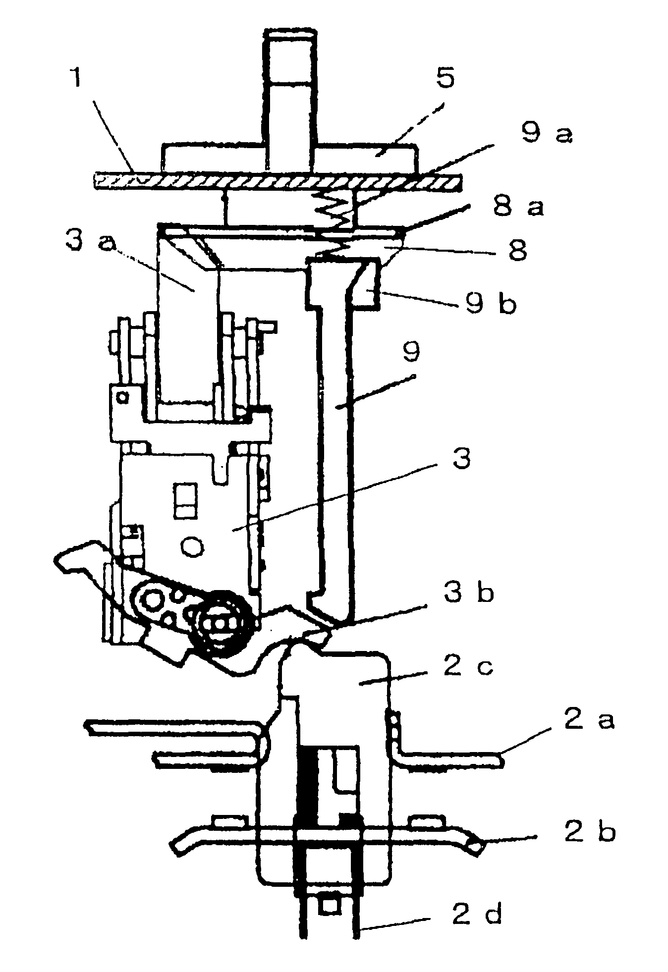
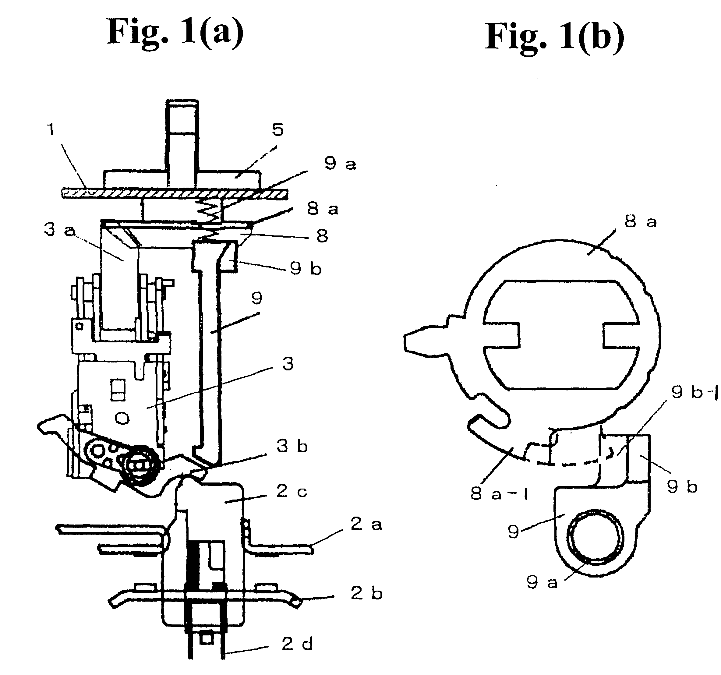
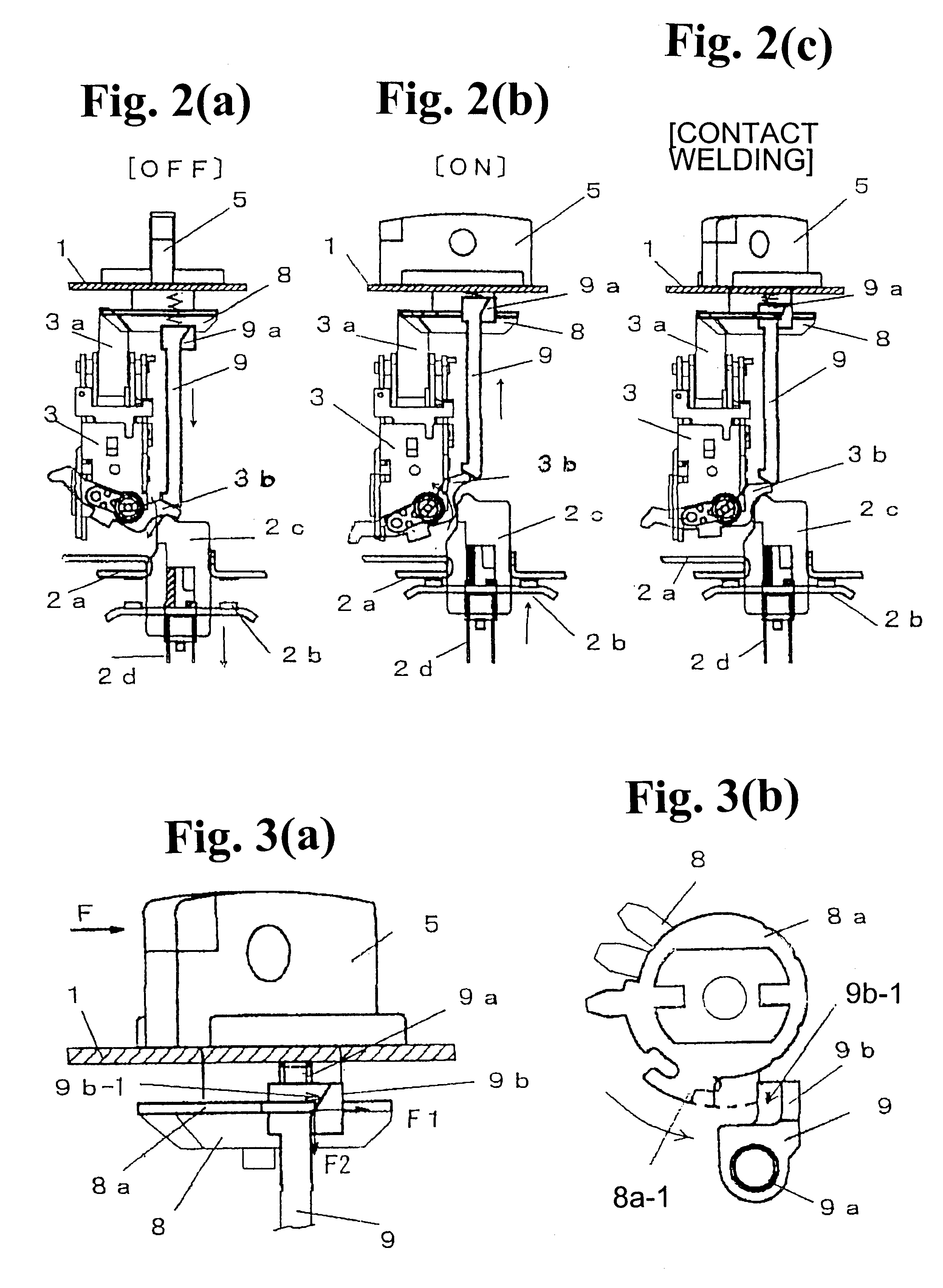
As shown in FIGS. 1(a) and 1(b), in the illustrated embodiment, the handle lock lever 9 is separated from the opening and closing mechanism section 3, and is arranged so as to interconnect the tip of the opening and closing lever 3b projecting to the side from the opening and closing mechanism section 3 with a clutch gear 8a of the driving gear 8 located above the opening and closing lever and directly coupled to an operating handle 5, so that the handle lock lever 9 is supported and guided so as to move in the vertical direction. In the illustrated circuit breaker, the metallic clutch gear 8a, directly coupled to the shaft of the operating handle 5, is combined with the driving gear 8 of the gear mechanism for coup...


PUM


Abstract

In a circuit breaker, a rotary-operating handle is linked with an opening and closing mechanism via a driving gear so that main circuit contacts can be opened and closed by rotating an opening and closing lever. A vertically moving handle lock lever is arranged between a tip of the opening and closing lever and the driving gear directly coupled to the operating handle, so that when the main circuit contacts are opened after being welded, the lock lever abuts against the driving gear to restrain the operating handle to the vicinity of the ON position, thereby restricting the movement to a contact-open indicating position. Further, an upward-inclined surface is formed in a stopper section located at a tip of the lock lever, so that if the contact welding is not severe, the lock lever can be pushed down to forcibly open the contacts.

Description

BACKGROUND OF THE INVENTION AND RELATED ART STATEMENTThe present invention relates to a circuit breaker, such as an autobreaker applied to a control of an electric motor, in particular, to an interlock mechanism for indicating errors that allow an operator to identify an abnormal state of main circuit contacts caused by welding thereof, on the basis of a position of a rotary-operating handle.The basic structure of the autobreaker in which the present invention is implemented will be described with reference to FIGS. 4(a) to 4(d). In FIG. 4(a), reference numeral 1 denotes a breaker case, numeral 2 denotes a breaking section for main circuit contacts, numeral 3 is an opening and closing mechanism section, numeral 4 is an overcurrent tripping device, numeral 5 is a rotary-operating handle installed on a top surface of the case 1, numeral 6 is a gear mechanism for coupling the rotary-operating handle 5 to the opening and closing mechanism section 3 for transmission, and numeral 7 is an ...

Claims


Application Information

Patent Timeline
Patent Type & Authority Patents(United States)
IPC IPC(8): H01H71/10H01H71/56H01H71/50H01H89/06H01H89/08H01H3/32H01H3/40H01H73/28H01H73/12
CPCH01H71/56H01H71/501H01H3/40H01H89/08
Inventor HAMADA, YOSHINOBUKUBOYAMA, KATSUNORITAKAHASHI, TATSUNORIUCHIDA, NAOSHI
Owner FUJI ELECTRIC FA COMPONENTS & SYST CO LTD
Why Eureka
Try Eureka