Method and device for the encoding and decoding of power distribution at the outputs of a system

a power distribution and output technology, applied in the field of encoding/decoding of the power distribution at the outputs of a system, can solve the problems of power over 2 kw and the inability to implement an architecture of this kind

Inactive Publication Date: 2003-05-27
THALES SA
View PDF7 Cites 1 Cited by
  • Summary
  • Abstract
  • Description
  • Claims
  • Application Information

AI Technical Summary

Benefits of technology

This architecture also optimizes the power balance of a transmission chain by masking the switching function losses.
Furthermore, this architecture is less complex because it enables the use of components with standard specifications commonly used in the semiconductor industry.

Problems solved by technology

It is difficult and even impossible to implement an architecture of this kind for making fast (<200 ns) power switches with a peak power of over 2 kW.

Method used


Image

  • Method and device for the encoding and decoding of power distribution at the outputs of a system
  • Method and device for the encoding and decoding of power distribution at the outputs of a system
  • Method and device for the encoding and decoding of power distribution at the outputs of a system

Examples


Embodiment Construction

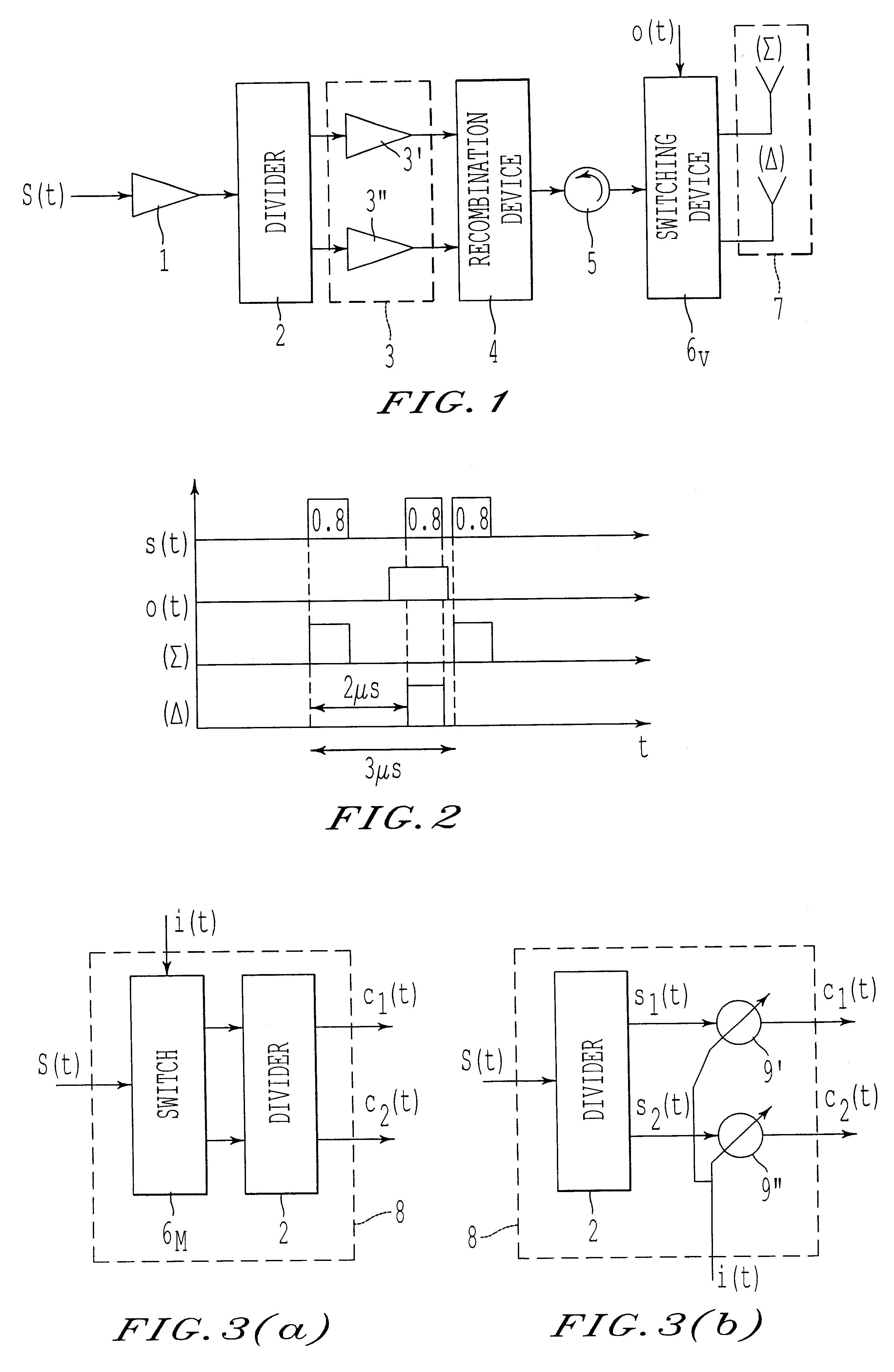
FIG. 3(a) shows an exemplary embodiment of a distribution encoder 8 according to the invention. This distribution encoder 8 has a switch 6.sub.M that receives a signal s(t) and a piece of distribution information element used to select one or more inputs of the divider 2. The divider 2, as its name indicates, divides the signal s(t) into two signals s.sub.1 (t) and s.sub.2 (t). The selection of one of the two inputs of the divider 2 by the switch 6.sub.M enables the piece of distribution information i(t) to be superposed on the signals s.sub.1 (t) and s.sub.2 (t). This superposing of this piece of distribution information i(t) on the signals s.sub.1 (t) and s.sub.2 (t) is done for example by means of a differential phase modulation between the parallel channels at output of the divider 2. The power division can then be carried out by a 3 dB / 90.degree. coupler whose properties are such that the piece of distribution information i(t) is superposed on the signal as described here above...


PUM


Abstract

In a method and device for the encoding / decoding of power distribution at outputs of a system, a distribution encoder includes an element that receives a useful input signal and a piece of distribution information, and that superposes the piece of distribution information received on the input signal. The piece of information is used for the subsequent distribution of the total power of the input signal at an output or outputs of the system. A distribution decoder includes one or more inputs that receive an encoded signal or an encoded signal divided into several signals including the useful signal and the piece of distribution information. Further, one or more outputs are connected to the outputs of the system to which the useful signal is transmitted by distributing the total power received according to the piece of distribution information. The method and device enable, for example, fast, low-power switching of the outputs of a high-power system and the programming of a system with variable power outputs.

Description

1. Field of the InventionThe invention relates to a method and device for the encoding / decoding of the power distribution at the outputs of a system. A possible application of the invention is the making of high-power transmitters such as for example those used by interrogators known as IFF (identification friend or foe) interrogators, using secondary radars.2. Description of the Prior ArtFIG. 1 shows that the current transmission chain used in IFF transmitter structures is constituted by the following elements in the following order: a driver 1, a two-channel power divider 2, a two-channel parallel amplification device 3 having an amplifier 3' and 3" on each channel, a two-channel recombination device 4, a circulator 5, a two-channel switching device 6.sub.v formed by PIN diodes and a transmission device 7 formed by two transmission antennas, one sum antenna .SIGMA. and one difference antenna .DELTA.. A switching command o(t) is applied to the signal s(t) through the output switchi...

Claims


Application Information

Patent Timeline
Patent Type & Authority Patents(United States)
IPC IPC(8): G01S7/03G01S7/28G01S7/282G01S13/00G01S13/78G01S13/44H04B7/005
CPCG01S7/03G01S7/282H04W52/42G01S13/78G01S13/44
Inventor ESPOSITO, PIERREQUEMIN, PATRICKRUFFENACH, OLIVIER
Owner THALES SA
Why Eureka
Try Eureka