Method and apparatus for improved noise attenuation in a dissipative internal combustion engine exhaust muffler

a technology of internal combustion engine and noise attenuation, which is applied in the direction of mechanical equipment, engines, machines/engines, etc., can solve the problems of entrain or "blow out" problem, create and cause turbulence and static pressure loss

Inactive Publication Date: 2003-06-03
QUIET STORM
View PDF120 Cites 34 Cited by
  • Summary
  • Abstract
  • Description
  • Claims
  • Application Information

AI Technical Summary

Problems solved by technology

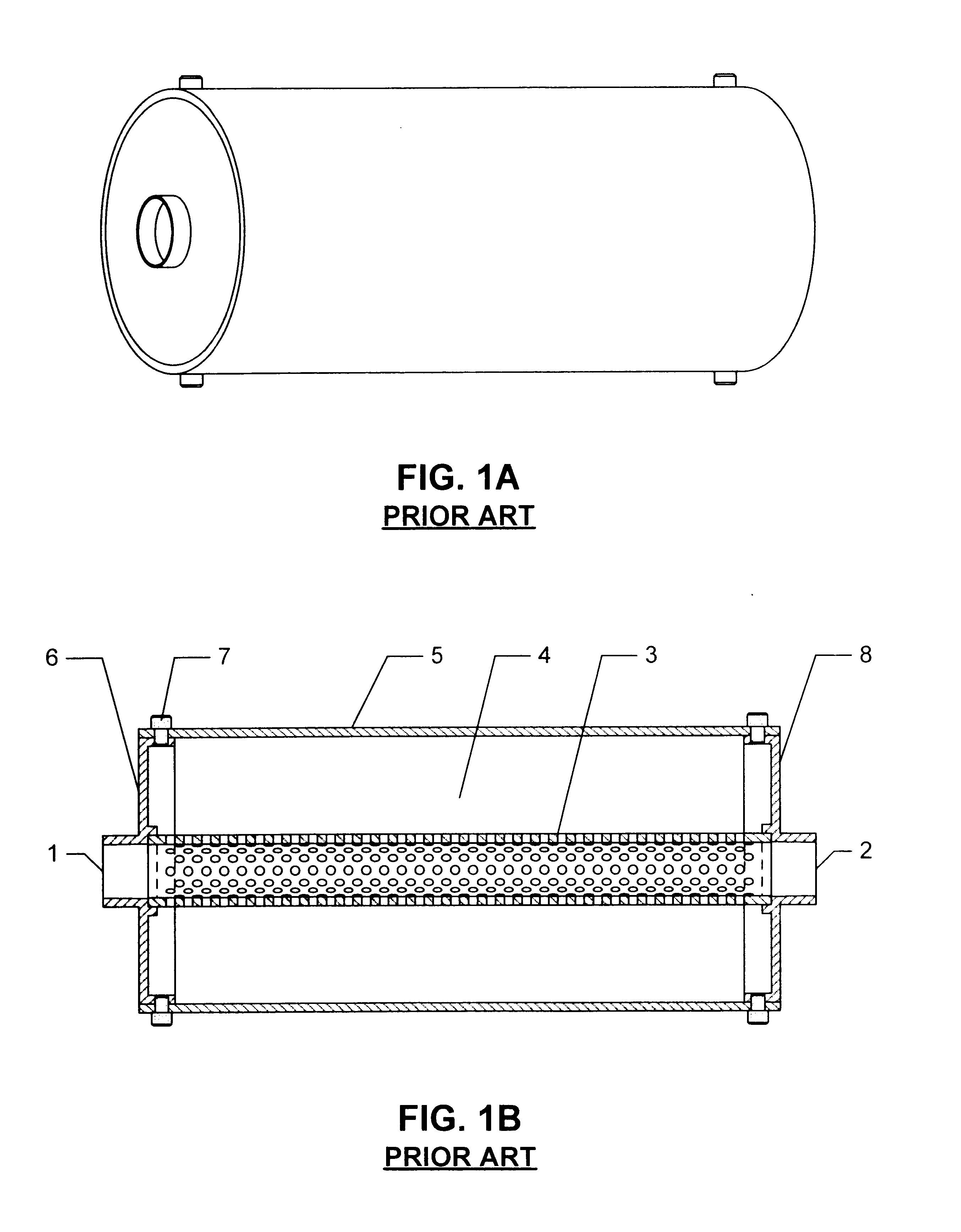
Not only does this diversion create turbulence and static pressure loss, it can actually entrain or "blow out" fill media through the perforations and through unsealed muffler casing-to-endcap connections.
This "blow out" problem is commonly encountered and well-known by users of conventional dissipative mufflers.
However, effective absorption coefficient drops dramatically in the low frequency end of the overall spectrum, with absorption worsening with increasing wavelength.
The resulting poor low frequency attenuation plagues all dissipative prior art designs utilizing perforated metal as a fill liner.
Such mufflers, however, can become quite complicated and heavy, as certain portions contain fill, while other portions have solid partitions.
Additionally, due to the reliance on reactive methods for low frequency attenuation, even the combination muffler designs suffer high pressure losses and reduce the engine's overall performance.
But while such means for linear occlusion may provide desirable improvements in sound reduction, there is usually a dramatic performance cost manifested by increased backpressure in the muffler.

Method used


Image

  • Method and apparatus for improved noise attenuation in a dissipative internal combustion engine exhaust muffler
  • Method and apparatus for improved noise attenuation in a dissipative internal combustion engine exhaust muffler
  • Method and apparatus for improved noise attenuation in a dissipative internal combustion engine exhaust muffler

Examples


Embodiment Construction

)

The present invention relates to mufflers for internal combustion engines. The invention overcomes the problems presented in conventional known mufflers through an innovative incorporation of specially configured elements, including components composed of metal fiber, or metallic felt, as described herein.

The primary function of the perforated tube duct in a conventional dissipative muffler is to convey sound waves from the exhaust flow to the surrounding annular chamber, which is filled with acoustically absorptive porous material. By acting as a liner in contact with the porous media (which shall be considered "rigid" as opposed to "flexible" since it is usually compressed between the perforated metal and the chamber wall), the perforated metal also affects the net absorption coefficient of the combination. It is known that such a combination of "resistive screen" and rigid porous media has a high absorption coefficient for mid to high frequencies (i.e., greater than 250 Hertz). ...


PUM


Abstract

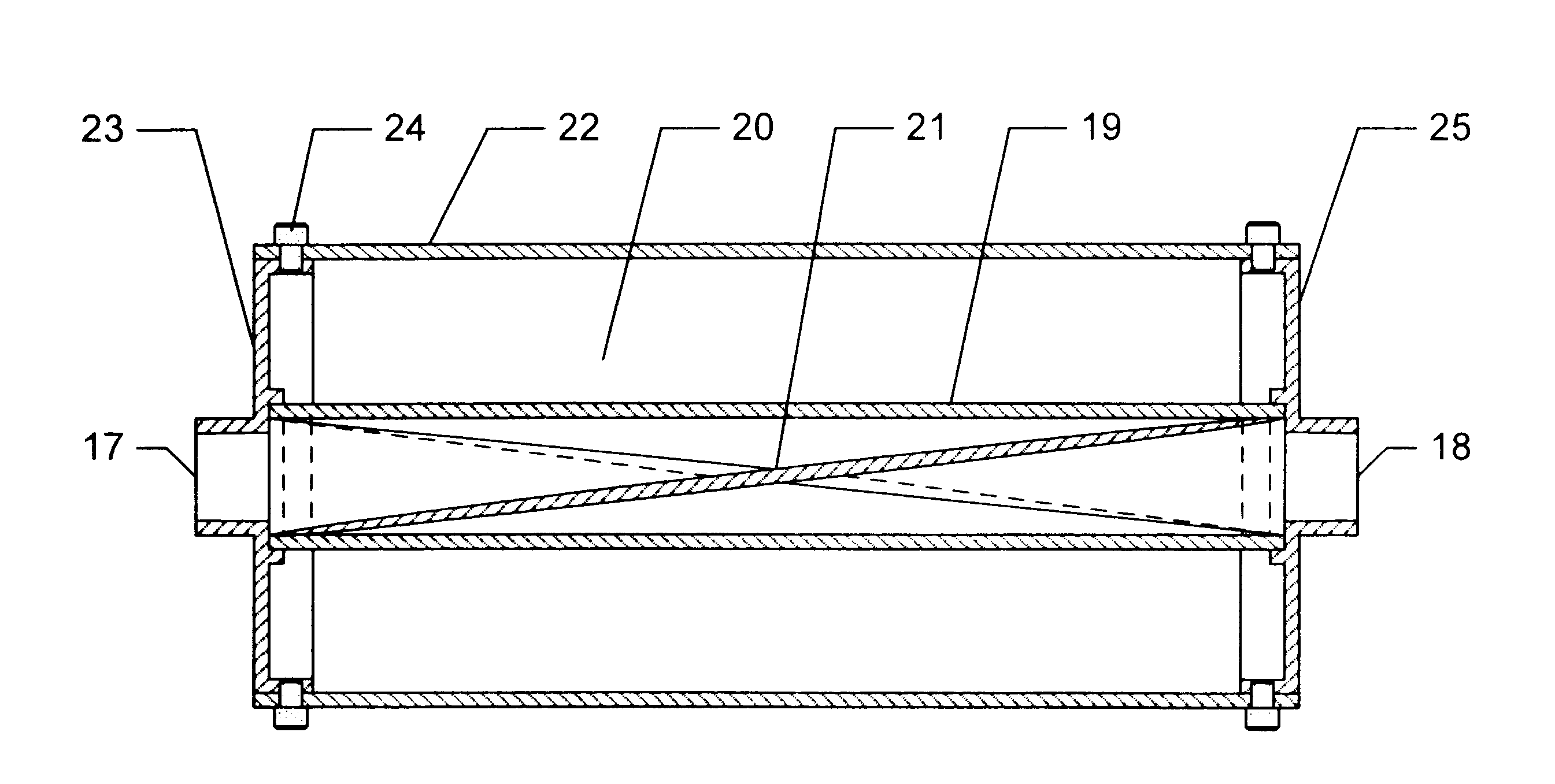
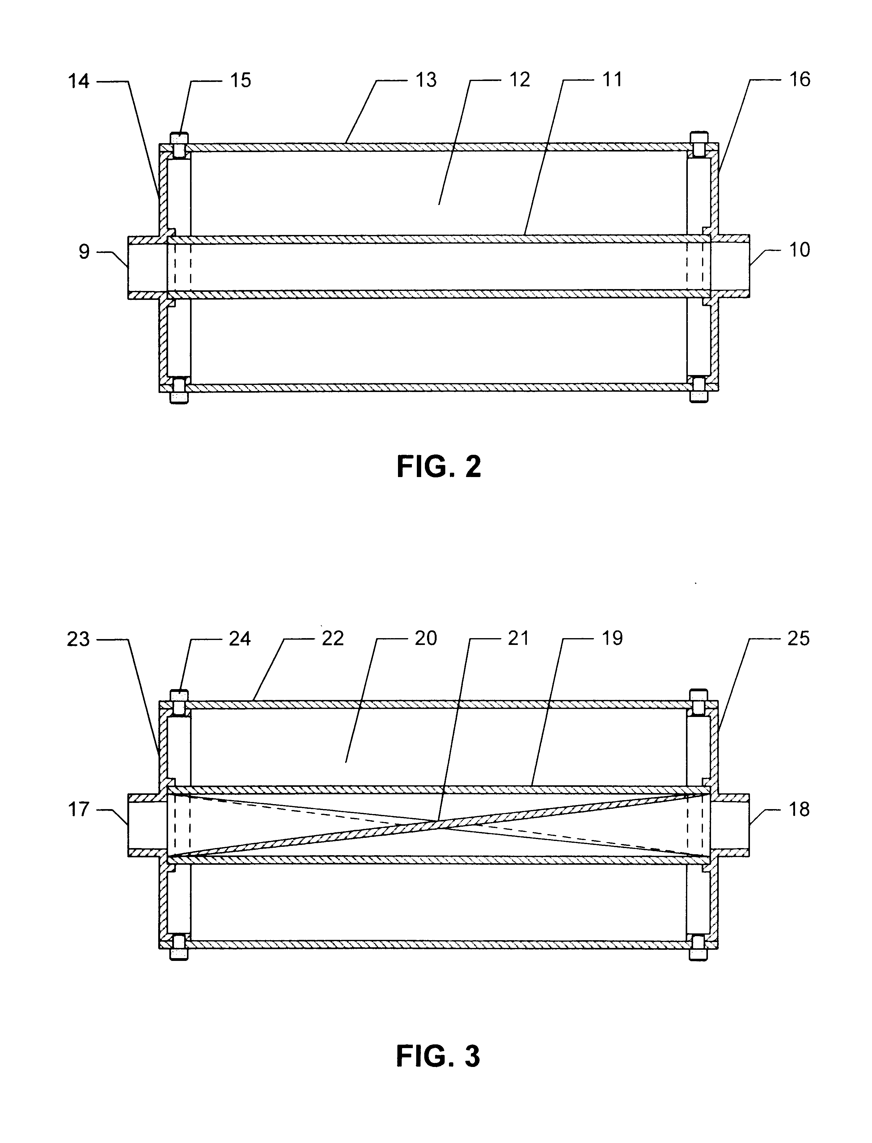
The use of fiber metal or similarly high flow resistance and high acoustic transparency material as a liner for traditional acoustically absorptive media in a dissipative muffler exhibits improved low frequency sound attenuation, reduces backpressure, and eliminates media entrainment or "blow-out" phenomenon which results in longer muffler life. The same class of materials may also be used to fashion an element that provides linear occlusion inside an otherwise line-of-sight type of muffler, where the occluding element provides improved impedance-matching acoustic absorption. Disclosed embodiments providing linear occlusion minimize traditional increases in muffler backpressure by incorporating helical, conical, and annular members in mufflers with round ducts. To maximize attenuation, a muffler according to the invention may feature both a fiber metal fill liner and a fiber metal linear occlusion element. Further, the liner that connects the inlet and outlet ports of the muffler may feature an offset, elbow, or turn that would simultaneously allow it to provide means for linear occlusion.

Description

1. Field of the Invention (Technical Field)The present invention relates generally to internal combustion engine (ICE) exhaust noise mufflers, specifically a dissipative muffler with improved maintenance, noise attenuation, durability features and reduced impact on engine efficiency.2. Background ArtPrior art shows dissipative mufflers, which are commonly composed of an inlet port fluidically connected to an outlet port by a duct that also forms the inner wall of an annular chamber containing acoustically absorptive fill. Currently, dissipative mufflers often use a perforated metal liner defining a duct that provides a boundary between the flow of gas and the surrounding volume of acoustically absorbent fill. In typical mufflers, the absorbent fill initially is contained between the inner duct and an outer casing. In some mufflers, a perforated metal duct serves as a backing or facing for a liner made from another material, e.g., fiberglass cloth.Some muffler apparatuses known in th...

Claims


Application Information

Patent Timeline
Patent Type & Authority Patents(United States)
IPC IPC(8): F01N1/10F01N1/24F01N1/08F01N7/16F01N7/00F01N1/04F01N1/12F01N3/021F01N3/06F01N13/16F01N13/18
CPCF01N1/04F01N1/085F01N1/10F01N1/125F01N1/24F01N13/16F01N13/18F01N13/1894F01N1/08F01N2450/30F01N3/021F01N3/06F01N2310/02F01N2310/04F01N2450/24
Inventor STORM, MARK
Owner QUIET STORM
Why Eureka
Try Eureka