Optical information medium and evaluation method

a technology of optical information and information layer, applied in the field of optical information media, can solve the problems of reducing the tolerance for the tilt of the information recording layer of the medium, establishing such a recording/reading system, and reducing the focal depth, so as to mar resistance, and improve the abrasion resistance.

Inactive Publication Date: 2003-06-10
TDK CORPARATION
View PDF6 Cites 46 Cited by
  • Summary
  • Abstract
  • Description
  • Claims
  • Application Information

AI Technical Summary

Benefits of technology

The present invention has been devised under the above-mentioned circumstances, and its object is to provide an optical information medium which is less susceptible to mar or flaw during the user's handling, and specifically, an optical information medium having a recording density increased due to the increased NA of a recording / reading optical system, which medium is less susceptible to mar or flaw by collision of a pickup during the recording and / or reading operation. Another object of the invention is to provide a method for evaluating the mar resistance of an optical information medium on its recording / reading light incident side surface, by quantitative determination in a state reflecting an actual service environment and in a simple way.

Problems solved by technology

However, several problems arise in establishing such a recording / reading system having increased NA.
One exemplary problem is a reduction of the tolerance for the tilt of the information recording layer of the medium.
Other problems associated with the increased NA are reduced focal depth and reduced working distance between the light-transparent substrate surface and the objective lens.
The focal depth decreases in inverse proportion to (NA).sup.2 and so, the focusing servo system is likely to become unstable and consequently, very sensitive to mechanical precision, flaws and stains on the light-transparent substrate surface.
Moreover, the working distance decreases as the NA increases, provided that the objective lens diameter is fixed, with the increased risk of collision of the pickup casing or objective lens against the light-transparent substrate surface.
For example, the system with NA=0.85 will have a focal depth of .+-.0.3 .mu.m and a working distance of about 100 to 300 .mu.m so that the focusing servo system is likely to become very unstable.
These resins are optically homogeneous, highly transparent, easily moldable and excellent in mechanical strength, but have drawbacks including a low surface hardness and mar susceptibility.
However, these resins of the UV curing type have a certain limit of surface hardness achievable, despite superior abrasion resistance as compared with thermoplastic resins including polycarbonate, and do not always provide fully satisfactory abrasion resistance for use as optical information media.
However, the inorganic film formed by such a technique as sputtering or evaporation has increased internal stresses.
Then, when the film is grown to a thickness of more than several hundreds of nanometers in order to establish satisfactory abrasion resistance, the film becomes self-destructible.
Then the inorganic film of this type is difficult to provide a hard coat layer having substantially satisfactory abrasion resistance.
It is then difficult to apply this method to the surface of light-transparent substrates made of less heat resistant resins.
However, this evaluation method offers macroscopic evaluation using incoherent light, that is, non-convergent light, which is not always correlated to the degree of deterioration of recording / reading characteristics of the optical information medium caused by abrasion.
Therefore, the above method is not regarded as an appropriate method of evaluating the performance of a hard coat layer on an optical information medium.
Heretofore, there has not been available a method of evaluating or inspecting a hard coat layer while meeting various requirements as mentioned above, and it has been impossible to ascertain the accurate performance of a hard coat layer.

Method used


Image

  • Optical information medium and evaluation method
  • Optical information medium and evaluation method
  • Optical information medium and evaluation method

Examples


example 1

Inverse Laminate Type

Medium 1

Medium 1 having the same structure as FIG. 1 except that it was of the read only type was fabricated by the following procedure.

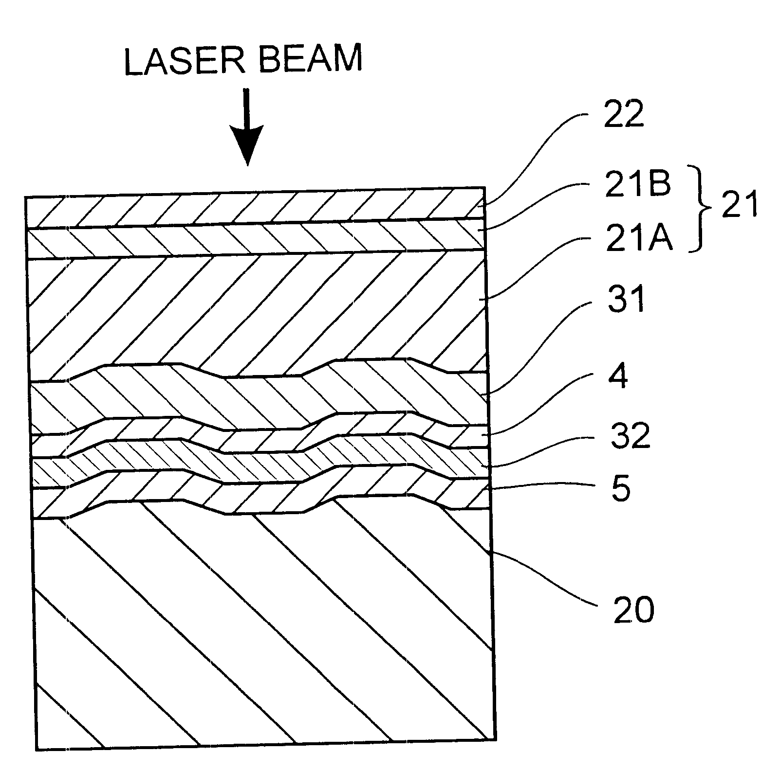
First, a polycarbonate substrate (outer diameter 120 mm, thickness 1.2 mm) in the surface of which random signal data were previously formed as prepits was used as a supporting substrate 20. On the surface of the supporting substrate 20 where prepits were formed, a reflective layer of aluminum was deposited to a thickness of 100 nm by a sputtering technique. Then a coating of UV-curable resin (SD301 by Dainippon Ink & Chemicals, Inc.) was applied to a thickness of 100 .mu.m by a spin coating technique and cured with UV radiation to form a light-transparent substrate 21. It is noted that when the light-transparent substrate 21 after curing was peeled from the reflective layer and measured for tensile modulus, it had a tensile modulus of 970 MPa.

Next, on the light-transparent substrate 21, a xylene solution of inorganic polysilaza...

example 2

Medium 4

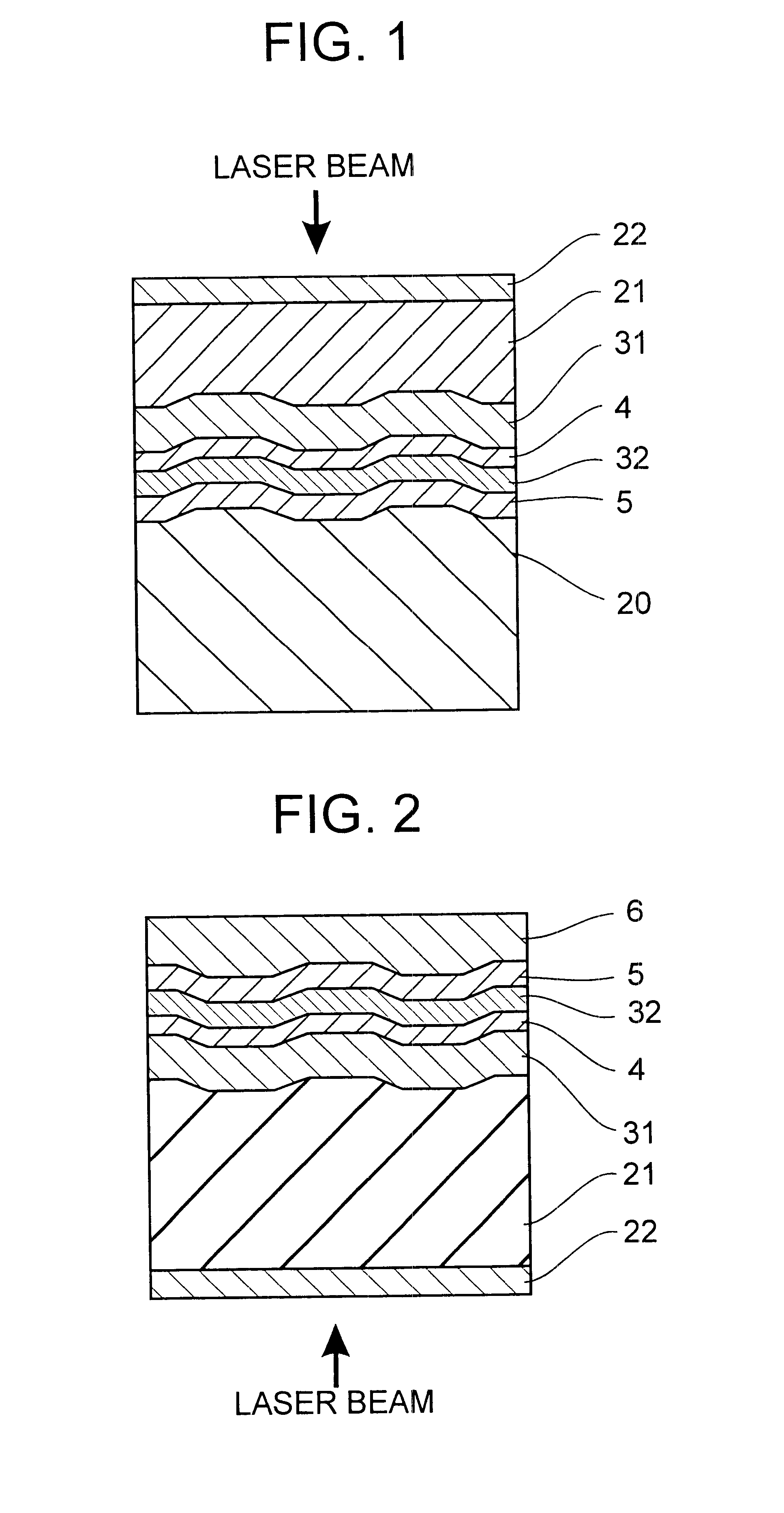
A commercially available DVD-RAM (recording capacity 2.6 GB / side) was furnished. DVD-RAM is a phase change recording medium and has substantially the same structure as the medium shown in FIG. 2, two of which are joined together with the protective layers 6 abutted. The recording layer 4 is composed mainly of Ge, Sb and Te and the light-transparent substrate 21 was a polycarbonate substrate of 0.6 mm thick.

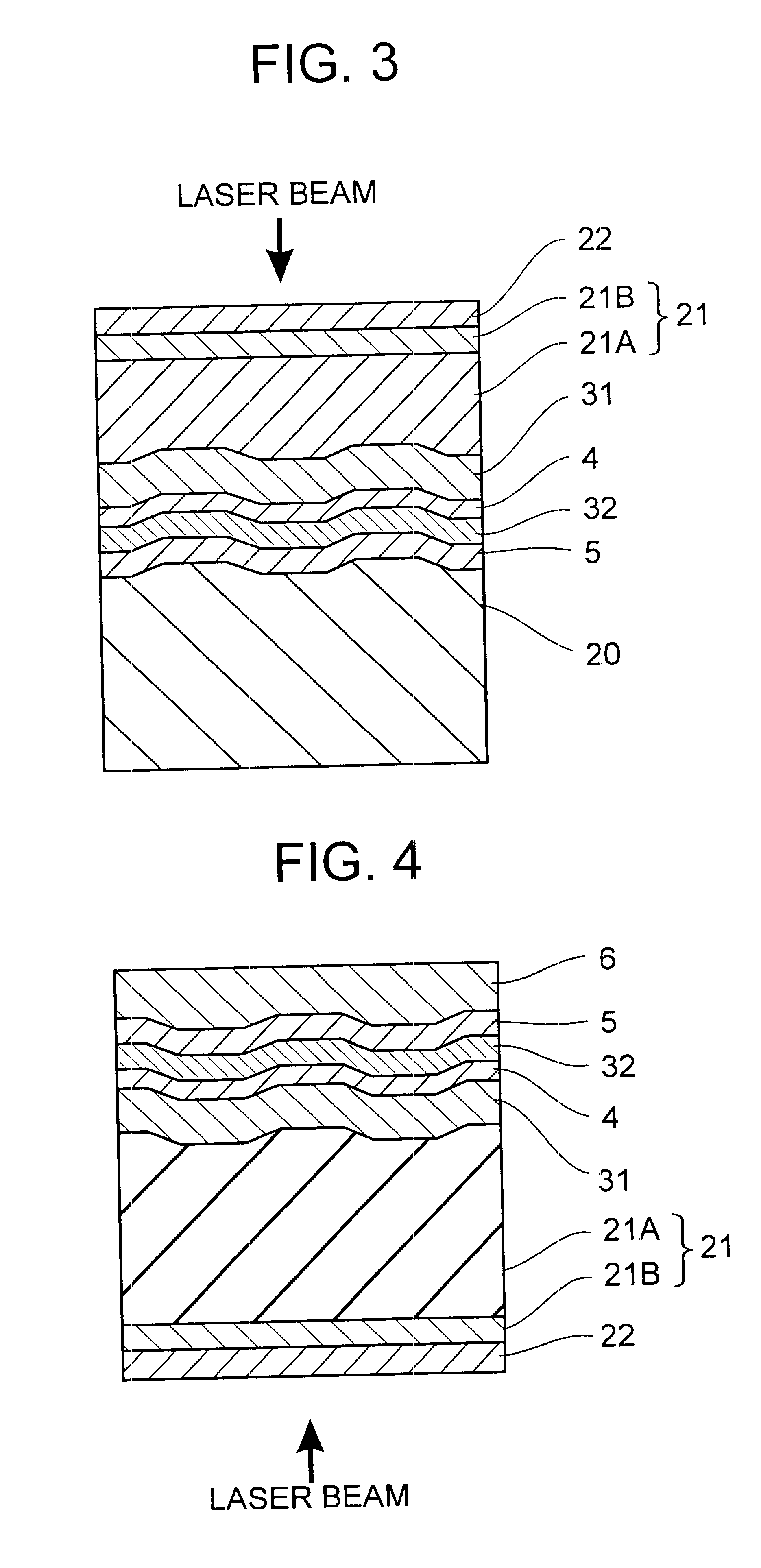
Using this DVD-RAM, Medium 4 having the structure shown in FIG. 4 was fabricated by the following procedure. With the polycarbonate substrate of DVD-RAM being regarded substrate body 21A, a UV-curable acrylic resin (HOD-3200 by Nippon Kayaku Co., Ltd.) was applied on its laser beam incident side surface by a spin coating technique and cured by irradiating UV radiation (high-pressure mercury lamp, dose 300 mJ / cm.sup.2), forming a barrier layer 21B of 3.3 .mu.m thick. The light-transparent substrate 21 had a tensile modulus of 1,340 MPa.

Subsequently, a cured polysilazane fil...

example 3

Medium 7

Medium 7 having the same structure as FIG. 6 except that it was of the read only type was fabricated by the following procedure.

First, a polycarbonate substrate (outer diameter 120 mm, thickness 0.6 mm) in the surface of which random signal data were previously formed as prepits was used as a substrate body 21A. On the surface of the substrate body 21A remote from the prepitted surface, a barrier layer 21B was formed as in Medium 4. The light-transparent substrate 21 had a tensile modulus of 1,340 MPa. Subsequently a cured polysilazane film 22 was formed on the surface of the barrier layer 21B as in Medium 1.

On the prepitted surface of the substrate, a reflective layer of aluminum (100 nm thick) was deposited by a sputtering technique. Then a prepit-free polycarbonate substrate (outer diameter 120 mm, thickness 0.6 mm) was joined to the surface of the reflective layer with a UV-curable adhesive (acrylic, adhesive layer after curing had a thickness of 5.0 .mu.m), completing a...


PUM

PropertyMeasurementUnit
thickaaaaaaaaaa
thicknessaaaaaaaaaa
thicknessaaaaaaaaaa

Abstract

An optical information medium has a light-transparent substrate and an information recording layer, wherein optical recording and / or reading is performed with a laser beam that enters the information recording layer from the light-transparent substrate side. A cured polysilazane film is disposed on the laser beam incident side of the light-transparent substrate, and the light-transparent substrate or the light-transparent substrate having the cured polysilazane film integrated thereon has a tensile modulus of at least 200 MPa. The medium on its laser beam incident side surface is improved in mar resistance.

Description

1. Technical FieldThis invention relates to optical information media such as read-only optical disks and optical recording disks, and a method for evaluating the mar resistance of the same.2. Background ArtTo accommodate a vast quantity of information as typified by moving image data, advanced optical information media are required to increase their recording density. Active research and development works have been made to achieve a higher density for increasing the recording capacity. Among such research works, one proposal relating to digital versatile disks (DVD) is to shorten the wavelength of recording / reading light and increase the numerical aperture (NA) of an objective lens, thereby reducing the focused spot diameter of recording / reading light. As compared with compact disks (CD), DVD is successful in achieving a recording capacity of 6 to 8 folds (typically 4.7 GB / side) by changing the recording / reading wavelength .lambda. from 780 nm to 650 nm and the numerical aperture f...

Claims


Application Information

Patent Timeline
Patent Type & Authority Patents(United States)
IPC IPC(8): B32B3/02G11B7/00G11B7/0037G11B7/253G11B7/24G11B11/00G11B7/007G11B11/105G11B7/24047G11B7/24067G11B7/241G11B7/254G11B7/2548G11B7/257G11B7/26
CPCB32B3/02G11B7/00375G11B7/2548G11B7/007G11B7/252G11B7/2534Y10T428/21G11B11/10584G11B2007/24312G11B2007/24314G11B2007/24316G01N3/56G11B7/2585B32B17/10211B32B2310/12B32B2307/416B32B2429/02
Inventor HAYASHIDA, NAOKIHIRATA, HIDEKITANAKA, TOSHIFUMI
Owner TDK CORPARATION
Why Eureka
Try Eureka