Method for driving source of liquid crystal display

a liquid crystal display and source technology, applied in the field of liquid crystal display, can solve the problems of increasing power consumption, and large amount of power consumption

Inactive Publication Date: 2003-06-10
SAMSUNG ELECTRONICS CO LTD
View PDF5 Cites 17 Cited by
  • Summary
  • Abstract
  • Description
  • Claims
  • Application Information

AI Technical Summary

Benefits of technology

An object of the present invention is to provide a method for driving the source lines of a liquid crystal display, which reduces consumption power required for polarity conversion accompanying a voltage swing with a wide width and, at the same time, decreases the driving consumption power of an amplifier.

Problems solved by technology

In case where the positive and negative video signals are alternately applied to the pixels on the bases of the VCOM, however, light transmission curves of the liquid crystal do not agree with each other, generating flicker.
The picture quality is good in the order of the frame inversion, line inversion, column inversion, and dot inversion, and the number of times of polarity change becomes larger in proportion to the picture quality, to result in the increases in power consumption.
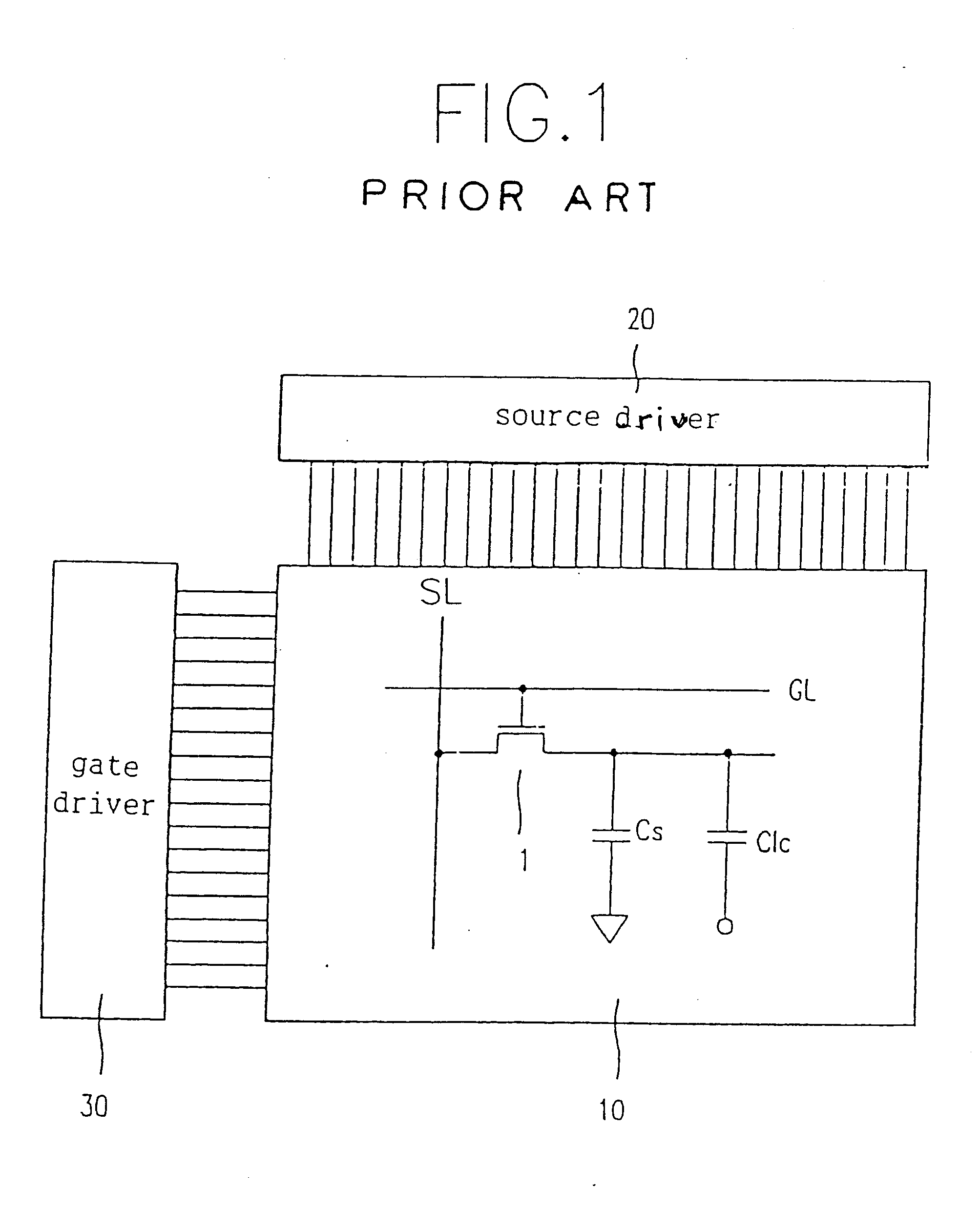
Accordingly, the conventional dot inversion consumes a large amount of power because the polarity of the video signal changes from positive to negative or from negative to positive on the basis of the VCOM at every time when the gate line GL is changed.
However, in the conventional method of driving the source of the LCD, a large amount of power consumption occurs at every two horizontal periods because the amount of power consumed for driving the source is proportional to the swing width of the video signal, requiring a large amount of consumption power.

Method used


Image

  • Method for driving source of liquid crystal display
  • Method for driving source of liquid crystal display
  • Method for driving source of liquid crystal display

Examples


Embodiment Construction

Reference will now be made in detail to the preferred embodiments of the present invention, examples of which are illustrated in the accompanying drawings.

FIG. 8 illustrates the operating range of a video signal according to the dot inversion mode in accordance with the present invention.

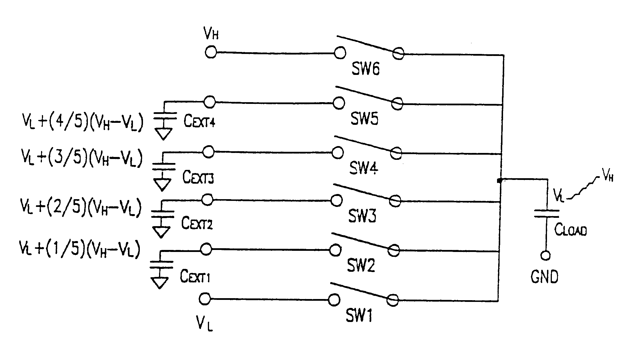
In the stepwise source driving method as a source driving method for a TFT-LCD according to the present invention, the transmission of a video signal is performed, being divided into 2-phase of polarity modulation and gray scale decision. Referring to FIG. 8, a voltage swing B ranging between a voltage VL corresponding to the medium gray of the negative video signal and a voltage VH corresponding to the medium gray of the positive video signal is executed according to the polarity modulation, and then voltage swings C and D for deciding gray scale are accomplished by an amplifier of a source driver. Here, the voltages VL and VH are not needed to be limited to the medium voltages of the negative and ...


PUM

PropertyMeasurementUnit
timeaaaaaaaaaa
timeaaaaaaaaaa
channel lengthaaaaaaaaaa

Abstract

There is provided a source driving method in a liquid crystal display, which applies negative and positive video signals to source lines of the liquid crystal display including a first and second plates and a liquid crystal being inserted therebetween, in which each video signal is applied, with its voltage being divided two phases of polarity modulation and gray scale decision. The polarity modulation is accomplished through stepwise charging and discharging.

Description

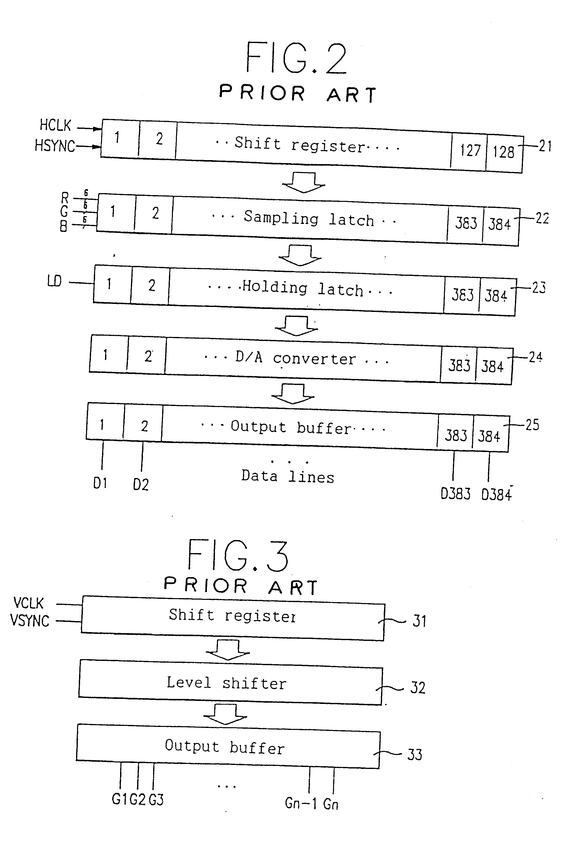
1. Field of the InventionThe present invention relates to a liquid crystal display, in more particular, to a method for driving the source lines of a liquid crystal display, which reduces the consumption power thereof.2. Discussion of Related ArtA liquid crystal display (LCD) draws growing attentions as a display device for displaying video signals and studies and researches for this device are being actively carried out. In general, the LCD is roughly divided into a liquid crystal panel part and a driving part. The liquid crystal panel includes a lower glass plate on which pixel electrodes and thin film transistors (TFTs) are arranged in matrix form, a upper glass plate on which a common electrode and a color filter layer are formed, and a liquid crystal layer filled between the upper and the lower glass plates.The driving part includes a video signal processor for processing video signals externally inputted, a controller for receiving a composite synchronous signal outputted from...

Claims


Application Information

Patent Timeline
Patent Type & Authority Patents(United States)
IPC IPC(8): G09G3/36G02F1/133G09G3/20H04N5/66
CPCG09G3/2011G09G3/3614G09G3/3688G09G3/3677G09G2330/023G09G2310/0248G09G2310/0297G09G2320/0247G09G3/36
Inventor KWON, OH-KYONG
Owner SAMSUNG ELECTRONICS CO LTD
Why Eureka
Try Eureka