Omni direction vehicle

a technology of omni-direction vehicles and wheels, applied in the field of wheeled vehicles, can solve the problems of lack of tractive force of the 608 vehicle, loss of directional control, and inability to provide directional stability, and achieve the effect of improving maneuverability

Inactive Publication Date: 2003-06-24
HAMMONDS TECHN SERVICES
View PDF21 Cites 43 Cited by
  • Summary
  • Abstract
  • Description
  • Claims
  • Application Information

AI Technical Summary

Benefits of technology

A primary object of this invention is to provide a service vehicle that has enhanced maneuverability.
The arrangement of a substantially outer circular shape of a vehicle with a smooth and unobstructed outer perimeter in combination with two, independently variable speed bi-directional drive wheels located on a single axis through the exact center of the vehicle and mobile connecting point or hitch that is free to move about the full circumference of the vehicle working in conjunction with a perpendicularly fixed connecting bar results in a tow vehicle characterized by the ability to move omni-directionally about a given point, change directions with zero maneuvering room beyond the physical footprint of the vehicle, and push or pull other mobile vehicles with precise control. Such characteristics reduces the operating space on the ground required to move or handle an object being manipulated thus increasing operating efficiency. Safety is increased because the operator of such a vehicle, positioned directly at the center of the tow vehicle, can always be facing the direction the vehicle is moving, never having to back up and look backward.

Problems solved by technology

Furthermore, the '608 vehicle lacks tractive force because of the single drive wheel.
Furthermore, a single drive wheel must be rotated in order to change the vehicle direction, and although the single drive wheel can be turned to direct the vehicle in any direction, it does not provide directional stability for the case where a force is exerted on the vehicle from an angle to the line of intended travel.
For example, a force against the '608 vehicle at a 20.degree. angle to the right or left of the line of travel would force the single '608 wheel to skid, causing loss of directional control.
A large turning radius makes maneuvering around crowded airport ramp areas difficult and often dangerous.
Operators are required to look over their shoulders in order to back up, and congestion is commonplace at airport and air service facilities.
Mowing vehicles share common problems with those of aircraft service vehicles.
Rolling over or tipping of such equipment is a common problem and safety hazard.

Method used


Image

  • Omni direction vehicle
  • Omni direction vehicle
  • Omni direction vehicle

Examples


Embodiment Construction

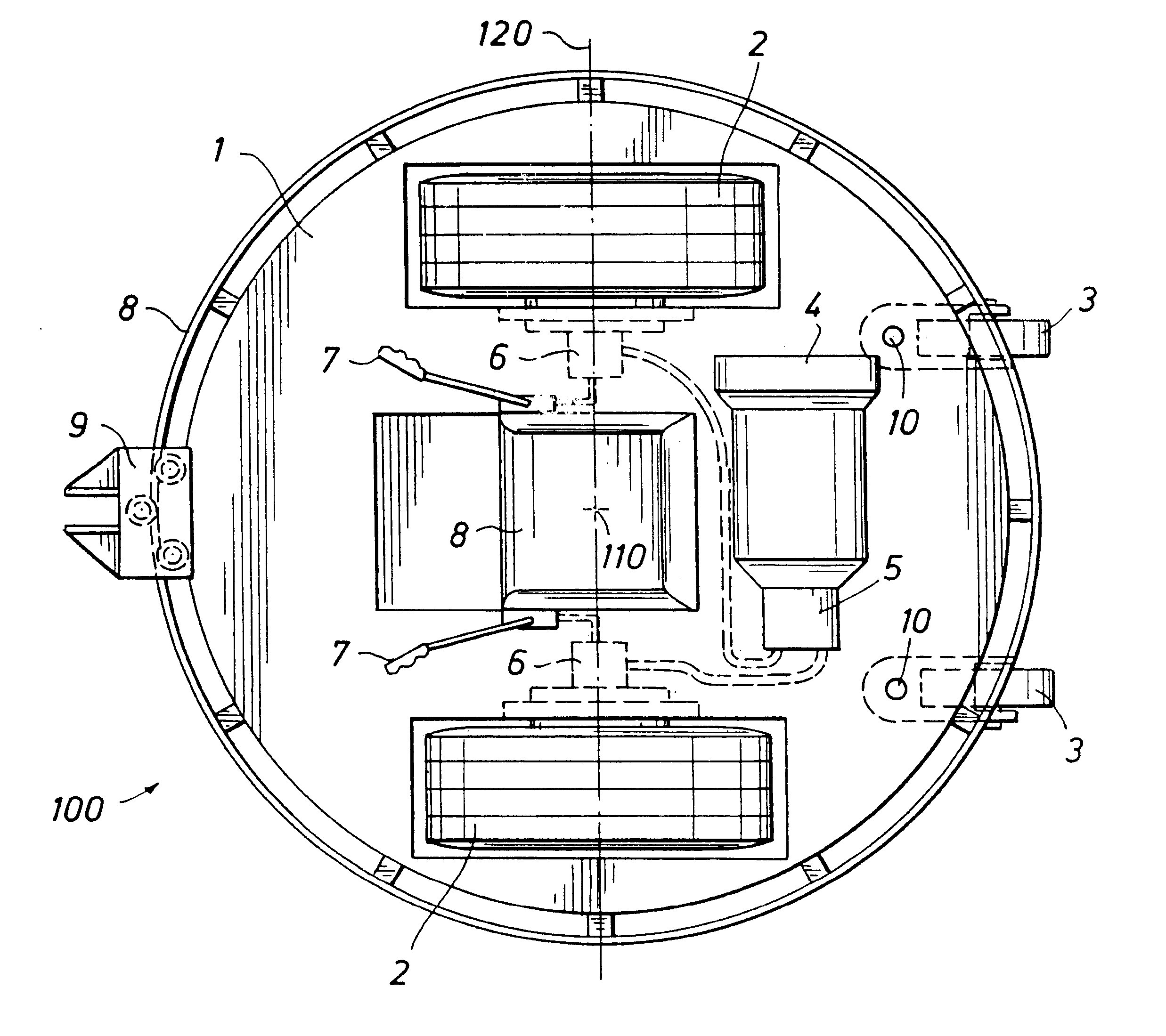
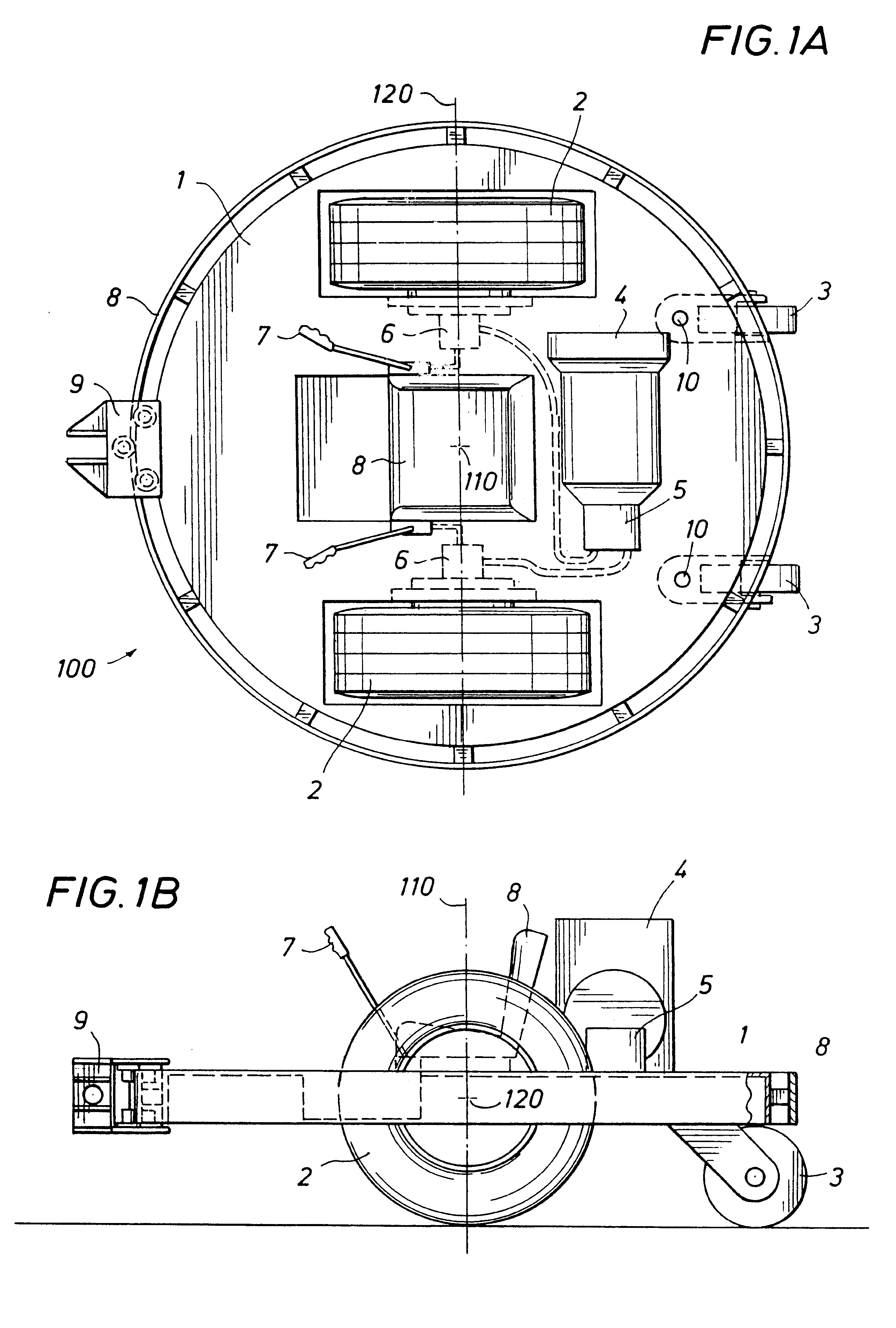
FIGS. 1A and 1B illustrate an Omni Directional Vehicle (hereafter ODV) according to the invention which includes primary wheels 2 mounted on a frame 1 which has an outer perimeter in the shape of a circle. The circular frame has a vertical axis 110, illustrated in FIG. 1B and which is perpendicular to the plane of the top view of FIG. 1A. The wheels 2 (powered in the powered version of FIGS. 1A, 1B, 3A, 3B, etc., but unpowered in the trailer version of FIG. 4) are mounted along a horizontal axis 120 which is perpendicular to the vertical axis 110 and intersects the vertical axis 110 as shown in FIGS. 1A and 1B. Two swivel castor wheels are pivotably mounted to the frame at the rear of the ODV 100.

In the powered version of the ODV 100, a power source 4 mounted on the frame 1 is provided for driving hydraulic pumps 5. The power source 4 may be a diesel or gasoline engine or an electric motor / battery assembly. The pump 5 provides balanced pressurized hydraulic fluid to separate hydraul...


PUM


Abstract

An omni direction vehicle with a frame having a round surface about its perimeter with no apparatus mounted on the frame extending beyond the perimeter. Two independent drive wheels located on an axis through the center of the frame are mounted at the same distance from a central vertical axis through the frame. Each wheel is powered independently of the other and can rotate at variable speeds in either direction. The vehicle is capable of movement in any direction by rotating the axis of the drive wheels to a position which is perpendicular to the desired direction of travel. The vehicle can spin about its vertical axis such that the axis of the drive wheels can be oriented at any direction without changing the original footprint of the space that the frame occupies over the ground. Thus, the vehicle requires a zero turning radius and requires only the space it occupies to change its forward orientation.

Description

1. Field of the InventionThis invention relates generally to a wheeled vehicle designed to turn about a vertical axis. In particular, the invention relates to powered utility riding vehicles of the type useful for aircraft servicing operations, airport passenger vehicles, lawnmowers, warehouse utility vehicles, wheelchairs, or in any vehicle where rotation-in-place steering is advantageous.2. Description of Prior ArtPrior art vehicles are known for turning with a zero turning radius, or so called "turning on the spot." U.S. Pat. No. 3,938,608 describes a vehicle with a single center mounted pivoting drive motor that is rotated about a vertical axis in order to change directions of the vehicle. The '608 vehicle is supported with three or more swivel wheels located at equal radial distances from the center wheel. The '608 outer profile is in the shape of a rectangle and has appendages that make close proximity maneuvering impossible next to another object such as a post or another veh...

Claims


Application Information

Patent Timeline
Patent Type & Authority Patents(United States)
IPC IPC(8): B64D1/00B64D1/22B64F1/32B62D61/00B62D11/06B64F1/00
CPCB62D11/06B62D61/00B64D1/22B66F9/07572B66F9/07545B66F9/07568B64F1/32B64F1/324
Inventor HAMMONDS, CARL L.
Owner HAMMONDS TECHN SERVICES
Why Eureka
Try Eureka