
Method and apparatus for conveying electrically conductive paints between different voltage potentials

a technology of electrically conductive paint and voltage potential, which is applied in the direction of electrostatic spraying apparatus, coating, liquid supply arrangement, etc., can solve the problems of inability to use in connection with automatic quick color-change system or require very complex control or monitoring functions

Inactive Publication Date: 2003-07-08
LACTEC GESELLSCHAFT FUR MODERNE LACKIERTECHNIK GMBH
View PDF11 Cites 51 Cited by
  • Summary
  • Abstract
  • Description
  • Claims
  • Application Information

AI Technical Summary

Benefits of technology

To this extent, also, the abovementioned object of the invention applies, namely to provide an apparatus which is constructed comparatively simply, manages with a low outlay on control and can also be used for automatic quick color-change systems.
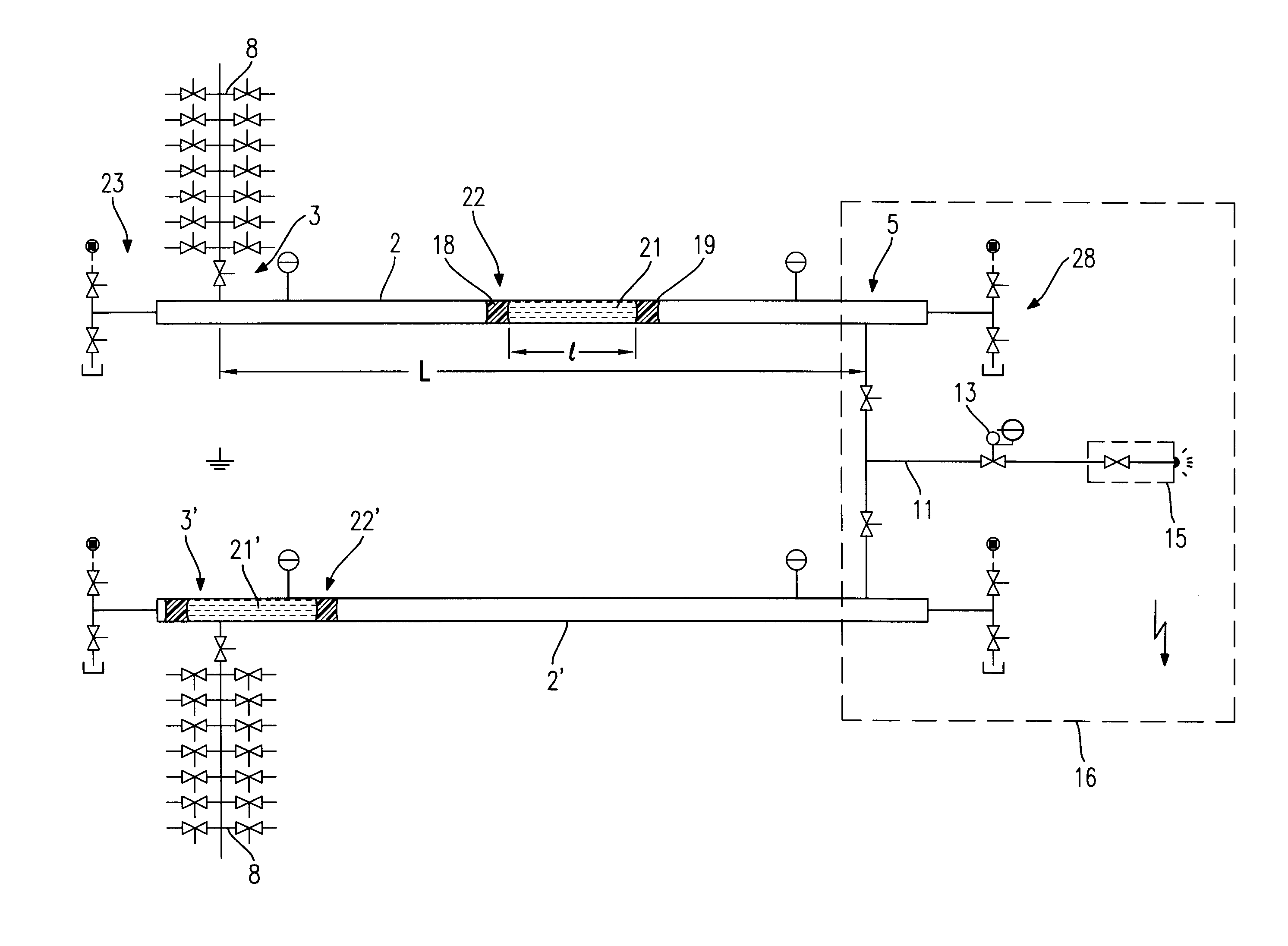
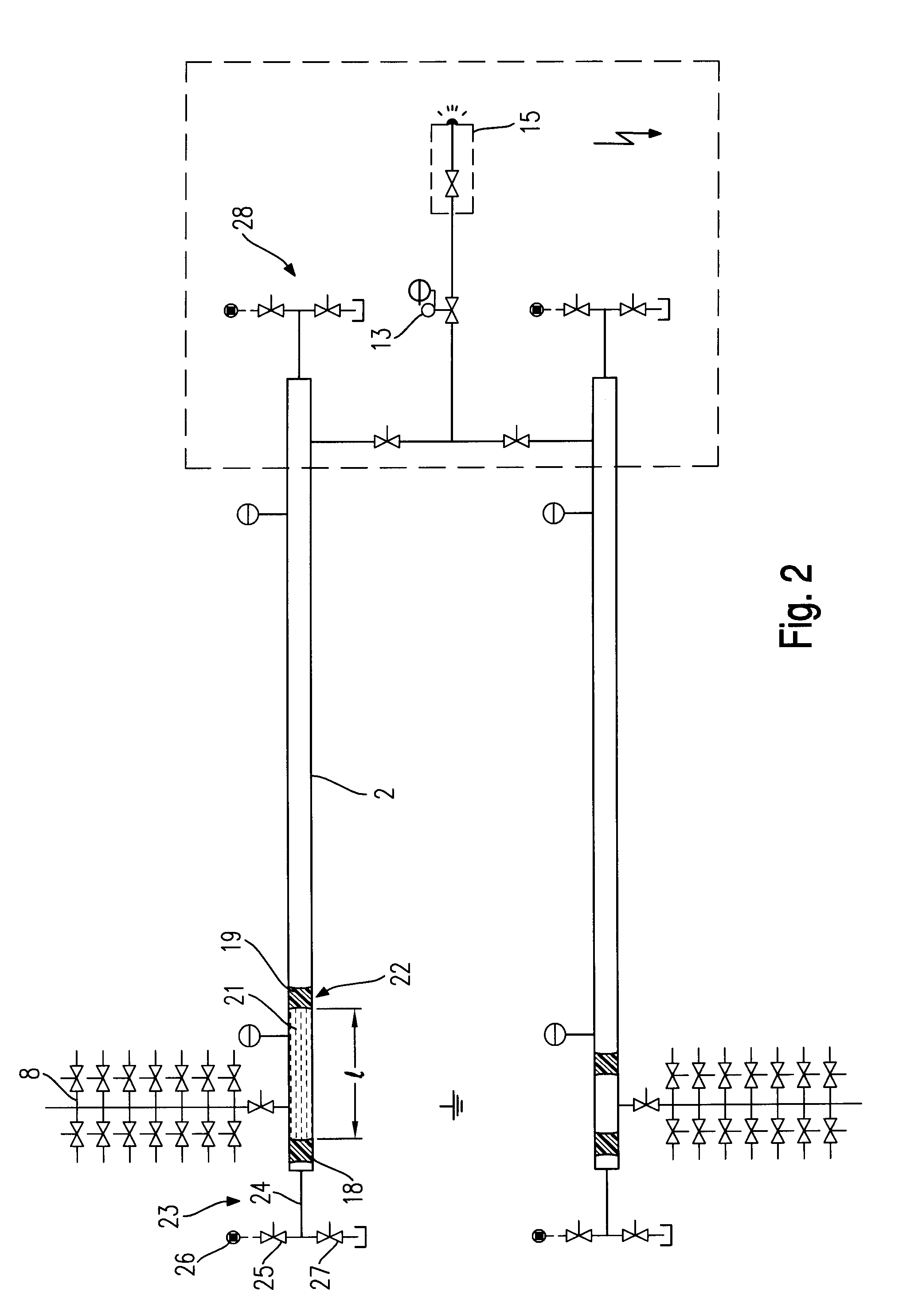
According to the invention, therefore, the paint is conveyed discontinuously in individual quantities, the longitudinal extent, measured in the conveying direction, of the individual units of paint being considerably below the length of the conveying path or the isolating conveying line, so that a sufficient isolating path always remains within the latter. Because of this measure, the individual quantities of paint or units of paint can be transported without difficulty into the high voltage area, for example by means of compressed air or an insulating liquid as a thrust medium, as outlined below using the exemplary embodiment. Since dividing up the quantities of paint does not raise any difficulties either, the method according to the invention and the associated apparatus prove to be fit for the purpose, simple and operationally reliable.

Problems solved by technology

The common factor in the known methods is that they either require very complex control or monitoring functions or cannot be used in connection with automatic quick color-change systems.

Method used


Image

  • Method and apparatus for conveying electrically conductive paints between different voltage potentials
  • Method and apparatus for conveying electrically conductive paints between different voltage potentials
  • Method and apparatus for conveying electrically conductive paints between different voltage potentials

Examples


Embodiment Construction

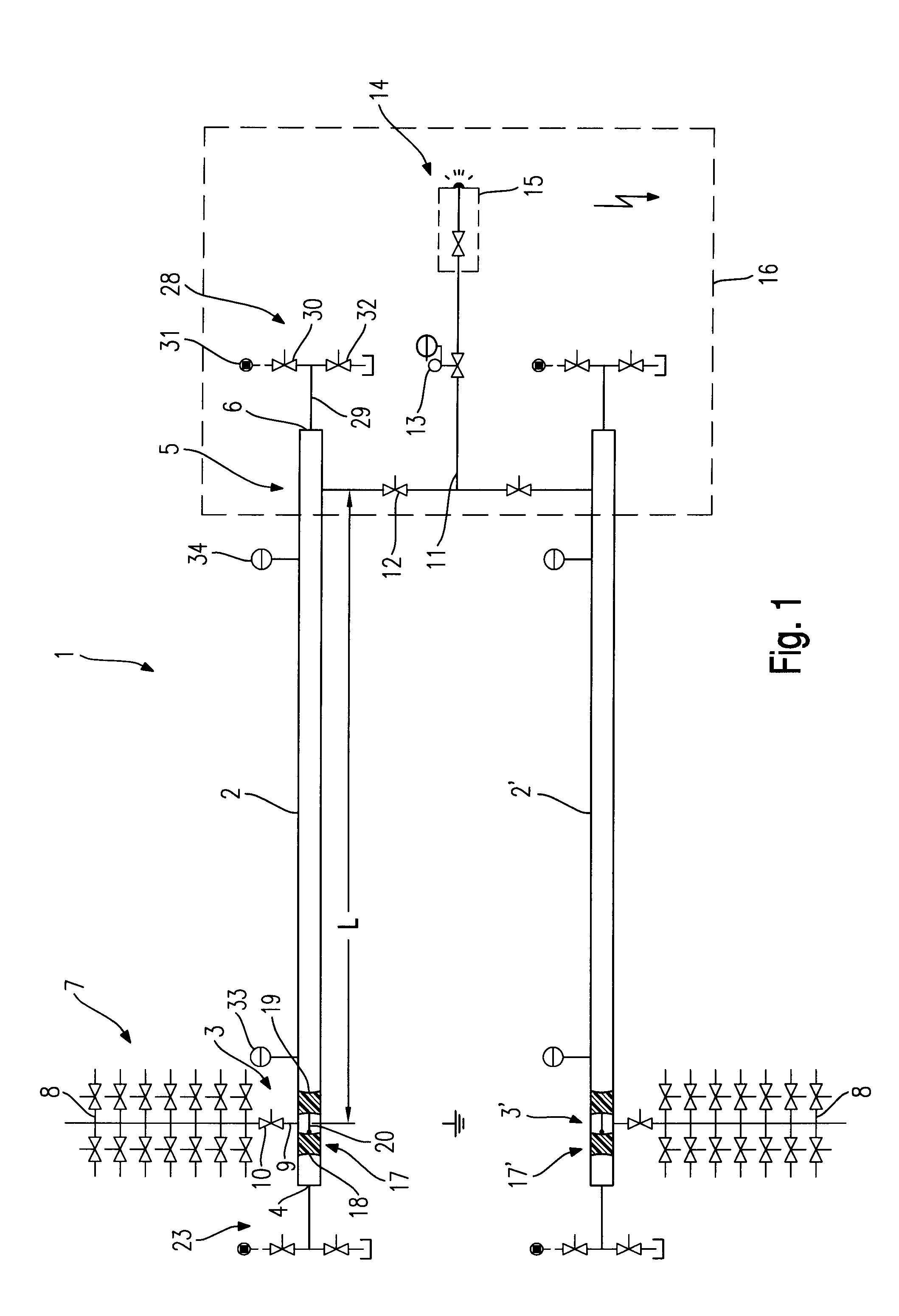
According to FIG. 1, the conveying apparatus 1 comprises a conveying line 2 with a loading station 3 close to the rear end 4 of the line, and a discharge station 5 close to the front end 6 of the line. The conveying line 2 is produced from an electrically insulating material, for example plastic, and has a comparatively great length L between the loading station 3 and the discharge station 5.

A supply system 7 for paint, which is constructed as an automatic color changer 8, is connected to the conveying line 2 via a supply line 9 with a supply valve 10 in the loading station 3.

In the discharge station 5, a discharge line 11 with a discharge valve 12 is connected to the conveying line 2. The discharge line 11 leads via a metering device 13 to a consumer 14, which is formed here by an electrostatic paint atomizer 15. There is high voltage across the latter, so that there is a high voltage area 16, which is indicated dashed and into which the discharge station 5 also falls. In contrast,...


PUM


Abstract

An electrostatic paint atomizer connected to a discharge station at high voltage is supplied, via an isolating conveying line, with individual divided-off quantities of paint enclosed between two pigs from a loading station at the other end of the conveying line. The paint is conveyed by a transport device supplying a thrust medium (compressed air or insulating liquid) to discharge the paint in the discharge station. A reverse transport device operating with compressed air transports the pigs back to the loading station. The length (L) of the conveying line between the loading and the discharge stations and the length (l) of a divided-off quantity of paint, are dimensioned to provide a sufficiently long isolating path (L-l) to avoid a voltage flashover. A continuous supply of paint is achieved with two parallel conveying lines, through which quantities of paint are metered with an offset from each other.

Description

The invention relates to a method for conveying electrically conductive paints from a supply system at ground potential, especially a color changer, to a consumer at high voltage, especially an electrostatic paint atomizer.BACKGROUND INFORMATIONThe electrostatic processing of electrically highly conductive paints, for example water-based paints, makes it necessary to transfer the paint from ground potential to high voltage potential, it being necessary to ensure electrical isolation between the potentials.For this purpose, various procedures are known and described, for example in U.S. Pat. No. 5,632,816 or DE 197 56 488, where operations are carried out with a paint supply lance which is moved into the paint discharge position through an insulating liquid.The common factor in the known methods is that they either require very complex control or monitoring functions or cannot be used in connection with automatic quick color-change systems.Accordingly, the invention is based on the o...

Claims


Application Information

Patent Timeline
Patent Type & Authority Patents(United States)
IPC IPC(8): B05B5/00B05B5/16B05B12/14B05B12/00
CPCB05B5/1616B05B12/14B05B12/1481B05B12/149
Inventor OTT, WINFRIED
Owner LACTEC GESELLSCHAFT FUR MODERNE LACKIERTECHNIK GMBH
Learn More