
X-ray examination apparatus with exposure control

Inactive Publication Date: 2003-07-15
KONINKLIJKE PHILIPS ELECTRONICS NV
View PDF7 Cites 36 Cited by
  • Summary
  • Abstract
  • Description
  • Claims
  • Application Information

AI Technical Summary

Benefits of technology

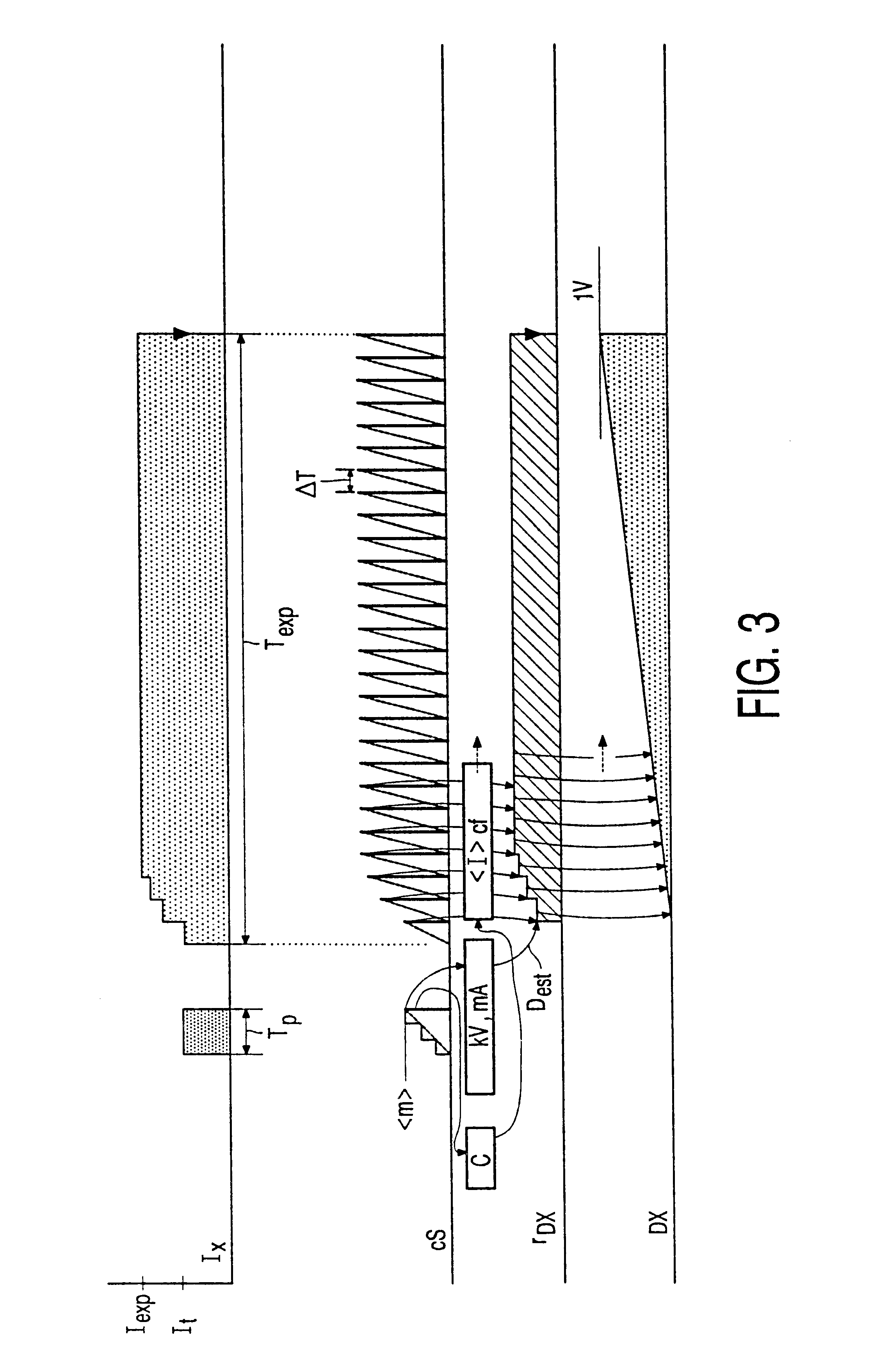
As the X-ray detector is adjusted to a coarser resolution during the test exposure, fewer signal values need be read out from the X-ray detector. Consequently, the time required to read out the X-ray detector is shorter. Moreover, only a smaller number of signal values, for example brightness values, need be processed in order to derive the control signal therefrom; consequently, less time will also be required to form the control signal. Because the X-ray examination apparatus according to the invention requires only a short period of time for the adjustment of the X-ray examination apparatus on the basis of the test exposure, the X-ray image will become available sooner. More specifically, only a short period of time elapses between the test exposure and the X-ray exposure. Consequently, changes are less likely to occur between the test exposure and the X-ray exposure, for example due to motion in or of the object to be examined. The X-ray examination apparatus according to the invention is thus capable of quickly forming an X-ray image while ensuring that the X-ray image has a high diagnostic quality. This means that small details of low contrast are clearly reproduced nevertheless in the X-ray image. The adjustment of the X-ray examination apparatus concerns notably the adjustment of the energy and the intensity of the X-rays emitted by the X-ray source.

Problems solved by technology

It is a drawback of the known X-ray examination apparatus that the reading out of the X-ray detector after the test exposure requires the same amount of time as the reading out after the X-ray exposure whereby the X-ray image is formed.
Consequently, the adjustment of the X-ray source for the X-ray exposure requires a comparatively long period of time.

Method used


Image

  • X-ray examination apparatus with exposure control
  • X-ray examination apparatus with exposure control
  • X-ray examination apparatus with exposure control

Examples


Embodiment Construction

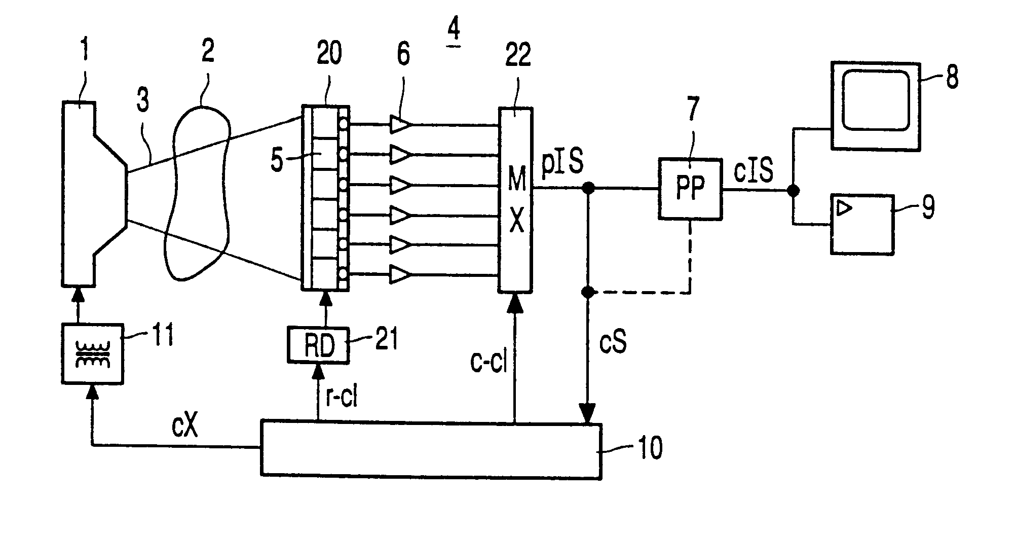
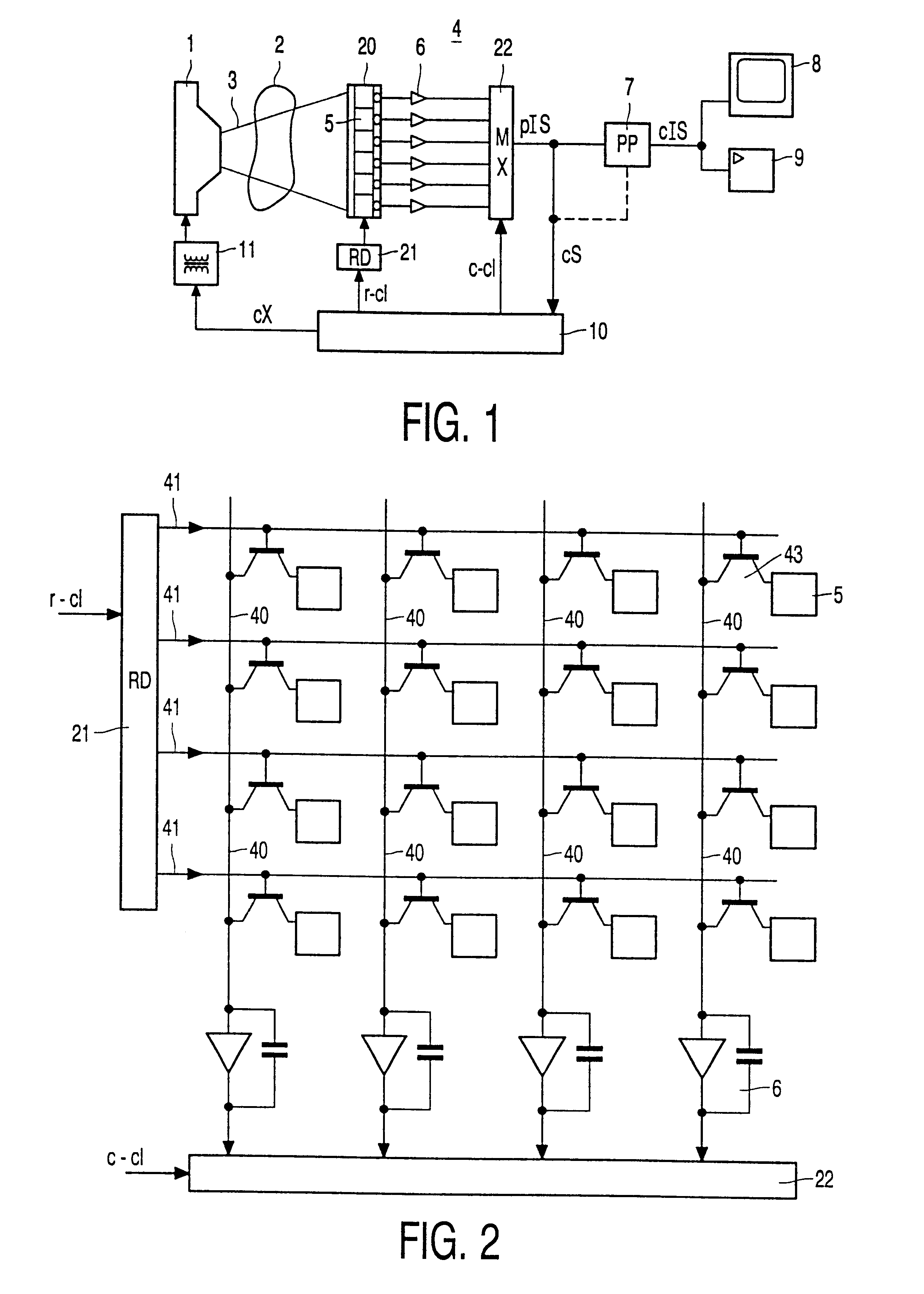
FIG. 1 shows diagrammatically an X-ray examination apparatus according to the invention. The X-ray source 1 emits an X-ray beam 3 which irradiates an object 2 to be examined, for example a patient to be radiologically examined. The X-ray image is formed on the X-ray detector as a result of local differences in the X-ray absorption within the patient 2. The X-ray detector in the present embodiment includes an X-ray sensitive solid state sensor matrix 20 with a large number of sensor elements 5 in which electric charge carriers are released by incident X-rays. The electric charges in the sensor elements are detected (read out) via read-out amplifiers 6 so as to be applied to a multiplexer (MX) 22. For example, the read-out amplifiers form column signals whose signal levels represent the electric charges in sensor elements in respective columns of the sensor matrix. The multiplexer combines the signal levels of the column signals so as to form a primary image signal (pIS) having signal...


PUM


Abstract

An X-ray examination apparatus includes an X-ray source, an X-ray detector and an exposure control system. The exposure control system is arranged to control the X-ray source so as to perform a test exposure at a low X-ray dose and to perform an X-ray exposure at a higher X-ray dose. The X-ray detector applies a control signal resulting from the test exposure to the exposure control system and the X-ray source is adjusted on the basis of this control signal. The X-ray exposure produces an X-ray image and the X-ray detector supplies an image signal representing this X-ray image. The exposure control system is arranged to adjust the X-ray detector to a low spatial resolution during the test exposure and to a high spatial resolution during the X-ray exposure. The X-ray detector preferably includes a sensor matrix having sensor elements arranged in columns and rows. The spatial resolution is adjusted by deriving the control signal and the image signal from large and small groups of sensor elements, respectively.

Description

1. Field of the InventionThe invention relates to an X-ray examination apparatus which includes an X-ray source, an X-ray detector, and an exposure control system for controlling the X-ray source and the X-ray detector, which exposure control system is arranged to control the X-ray source so as to carry out a test exposure with a low X-ray dose while producing a control signal by the X-ray detector, and to control the X-ray source on the basis of the control signal in order to carry out an X-ray exposure with a high X-ray dose and to acquire an X-ray image by the X-ray detector during this exposure.2. Description of the Related ArtAn X-ray examination apparatus known in the art is German Offenlegungsschrift DE 43 30 787.An object to be examined during a radiological examination, for example a patient to be examined, is exposed to an X-ray dose in order to form one or more X-ray images of the object. The X-ray dose required for individual patients to be examined is customarily adjust...

Claims


Application Information

Patent Timeline
IPC IPC(8): H05G1/46H05G1/30H05G1/00H05G1/44H05G1/42A61B6/00H05G1/38H05G1/58H05G1/64
CPCA61B6/488A61B6/542H05G1/30H05G1/42H05G1/44H05G1/46H04N5/32
Inventor ALVING, PETER LEXFABER, ALBERT LOUWJOOSTEN, JOHANNES HENRICUS MARIA
Owner KONINKLIJKE PHILIPS ELECTRONICS NV
Learn More