Method for calculating a distance between a well logging instrument and a formation boundary by inversion processing measurements from the logging instrument

a technology of formation boundary and distance, which is applied in the field of well logging instruments and measurement techniques, can solve the problems of inability to quantitatively accurately observe the horn, the prior art technique of observing the horn on electromagnetic propagation measurements has several limitations, and the assumption is often inaccura

Inactive Publication Date: 2003-07-15
SCHLUMBERGER TECH CORP
View PDF13 Cites 144 Cited by
  • Summary
  • Abstract
  • Description
  • Claims
  • Application Information

AI Technical Summary

Benefits of technology

In a particular embodiment, the inversion results at least one selected point along the trajectory are calculated to provide a Bayesian minimum uncertainty. This improves the accuracy of the inversion calculations.

Problems solved by technology

This assumption is often inaccurate, particularly in the case of horizontal wells whose ultimate horizontal extent may be several kilometers from the position of the pilot well or offset well.
Further, the prior art technique of observing horns on electromagnetic propagation measurements has several limitations.
First, observation of the horns has not proven to be quantitatively accurate.
Second, horns are generally observed on the well log only when the instrument is very close to the boundary.
Correction of the wellbore trajectory using horn observation techniques is often too late to avoid penetrating an undesirable layer of the earth formations, such as a water-bearing layer disposed below a hydrocarbon reservoir.
Anisotropy in the electric conductivity and dielectric permittivity of the layers of the earth formations make the quantitative use of resistivity horns even more difficult.
Generally, the inversion techniques known in the art, however, do not have as a primary purpose determining the position of the wellbore with respect to layer boundaries.

Method used


Image

  • Method for calculating a distance between a well logging instrument and a formation boundary by inversion processing measurements from the logging instrument
  • Method for calculating a distance between a well logging instrument and a formation boundary by inversion processing measurements from the logging instrument
  • Method for calculating a distance between a well logging instrument and a formation boundary by inversion processing measurements from the logging instrument

Examples


Embodiment Construction

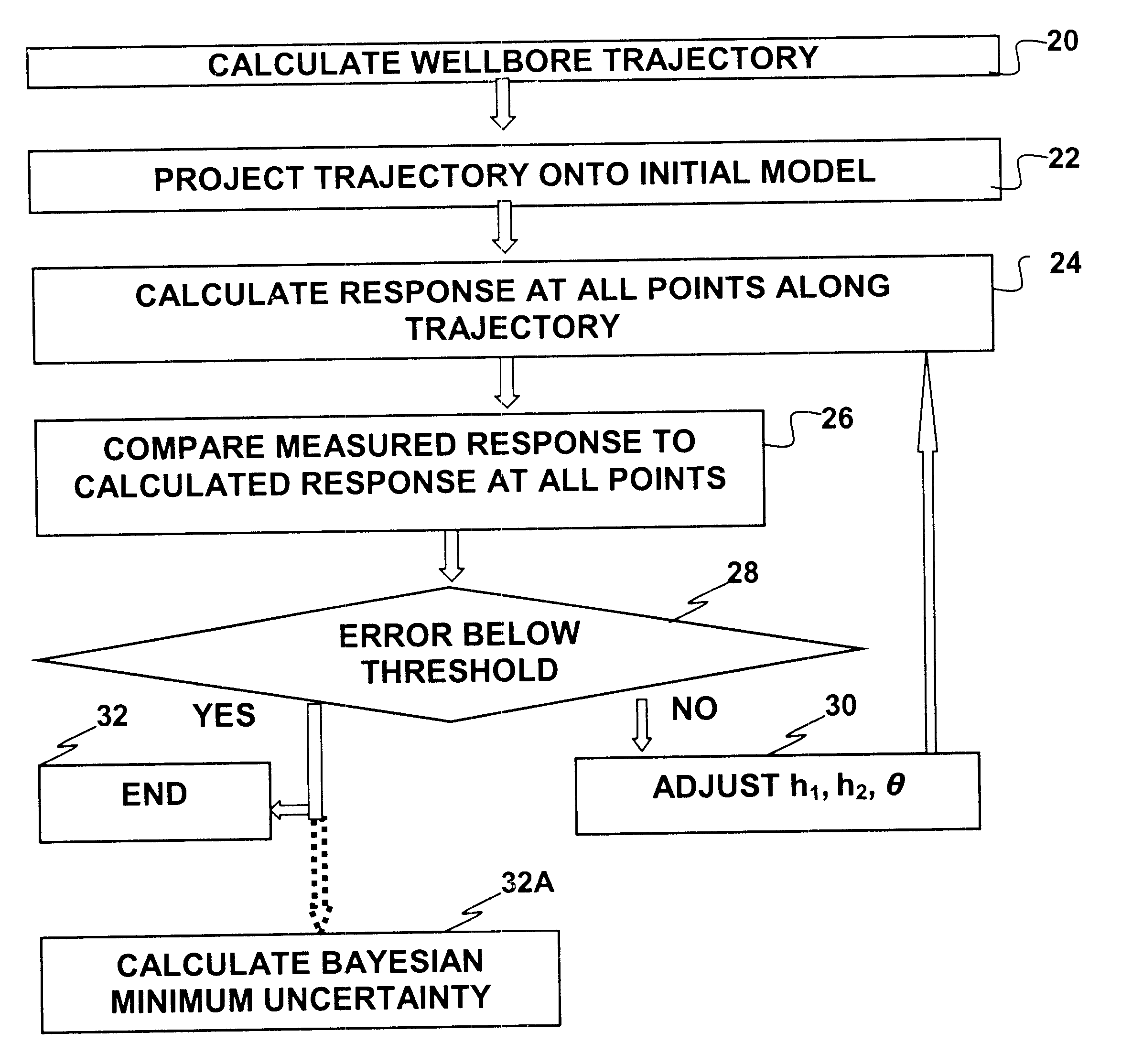
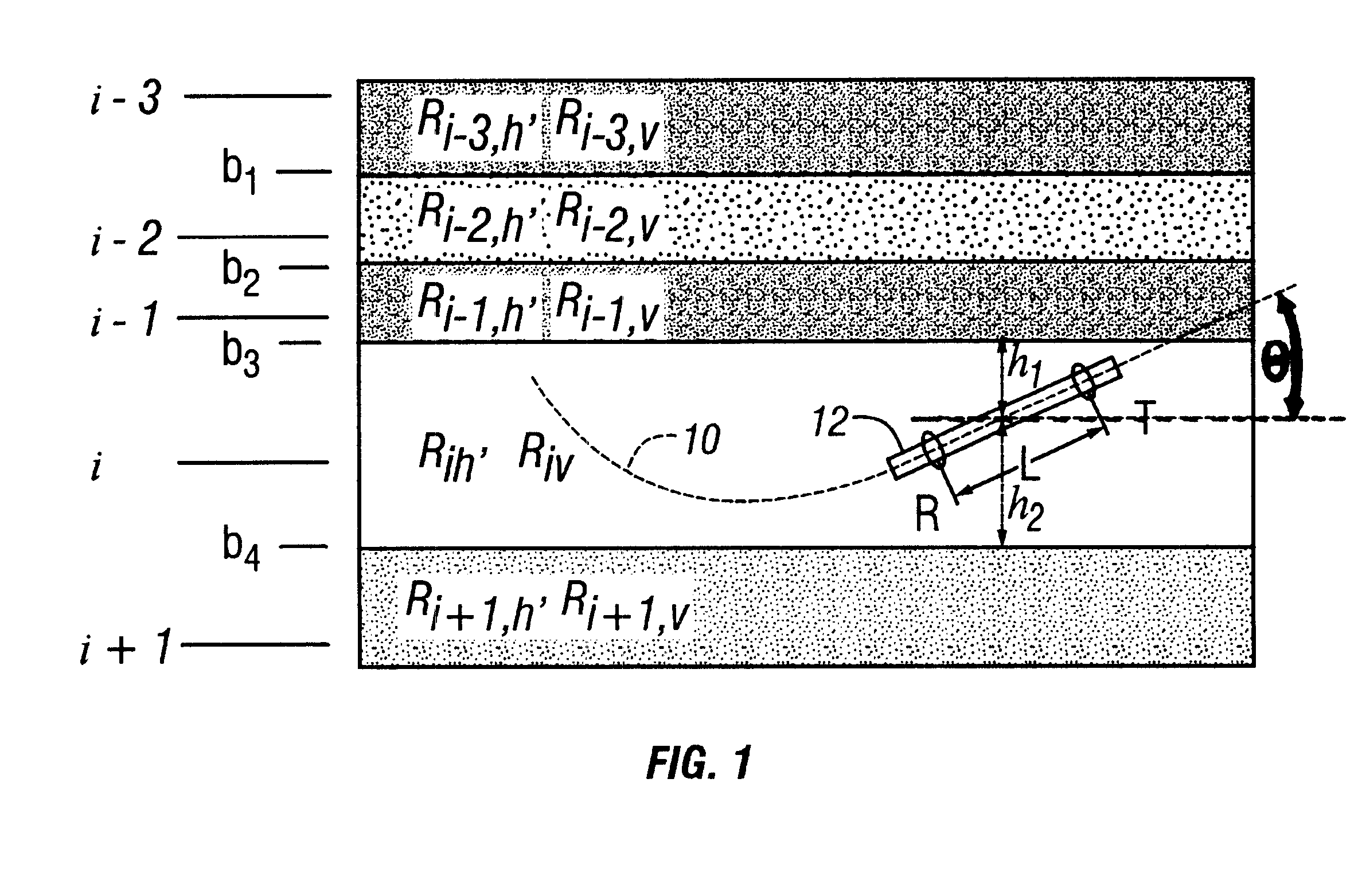
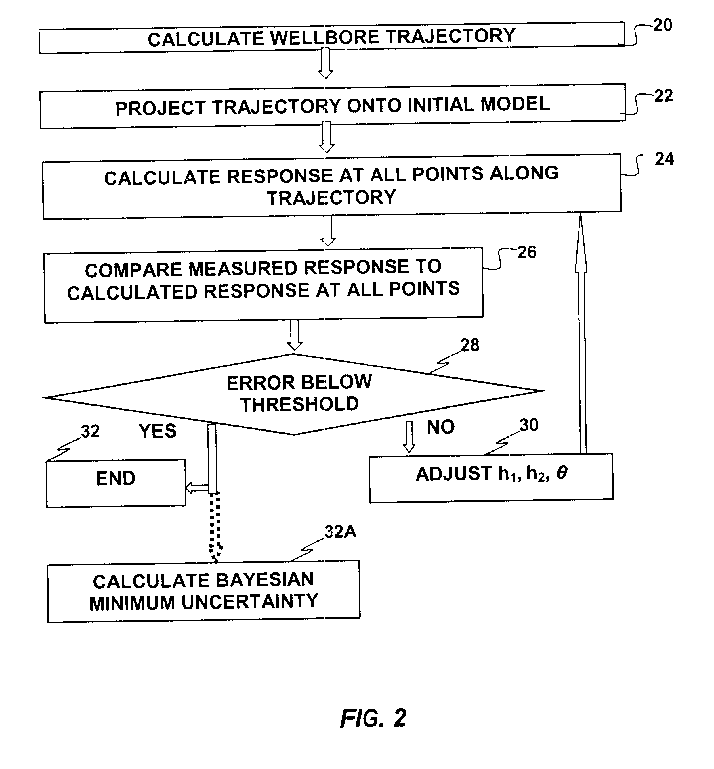
The invention, in general, is a method for determining a position of a well logging instrument with respect to a bed boundary (formation discontinuity) by inversion processing. Inversion processing generally includes making an initial estimate, or model, of the geometry of earth formations, and the properties of the formations, surrounding the well logging instrument. An expected logging instrument response is calculated based on the initial model. The calculated response is then compared with the measured response of the well logging instrument. Differences between the calculated response and the measured response are used to adjust the parameters of the initial model. The adjusted model is used to again calculate an expected response of the well logging instrument. The expected response for the adjusted model is compared to the measured instrument response, and any difference between them is used to again adjust the model. This process is repeated until the differences between the...


PUM

PropertyMeasurementUnit
trajectoryaaaaaaaaaa
resistivityaaaaaaaaaa
conductivityaaaaaaaaaa

Abstract

A method is disclosed for determining a position of a wellbore with respect to layer boundaries in earth formations. The method includes projecting a trajectory of the wellbore onto an initial model of the earth formations, selecting a segment of the trajectory and calculating along the segment expected responses of a well logging instrument. Differences between the expected responses and responses measured by the instrument along the segment are determined. The model is adjusted, the expected responses are recalculated and the differences are again determined. These are repeated until the differences fall below a selected threshold. In one embodiment, the trajectory of the wellbore can be adjusted to remain within a selected distance of a selected one of the layer boundaries.

Description

1. Field of the InventionThe invention is related generally to the field of well logging instruments and measurement techniques. More specifically, the invention is related to methods for processing signals from electromagnetic well logging instruments to determine a position of the instrument with respect to a conductivity discontinuity in earth formations surrounding the instrument.2. Description of the Related ArtWellbores drilled through earth formations to drain fluids such as petroleum are frequently drilled along a substantially horizontal trajectory in a petroleum reservoir to increase the drainage area in the reservoir. See, for example, MWD resistivity tool guides bit horizontally in thin bed, Oil and Gas Journal Dec. 9, 1991. Because petroleum reservoirs are frequently located in layered earth formations, the position of such substantially horizontal wellbores with respect to the boundaries of the layers in the earth formations often has a material effect on the productiv...

Claims


Application Information

Patent Timeline
Patent Type & Authority Patents(United States)
IPC IPC(8): G01V3/28G01V3/18E21B47/026E21B47/04G01V1/40
CPCG01V3/28
Inventor OMERAGIC, DZEVATHABASHY, TAREK M.ESMERSOY, CENGIZ
Owner SCHLUMBERGER TECH CORP
Why Eureka
Try Eureka