Water cooled air conditioner

a water-cooled air conditioner and air conditioner technology, applied in the field of water-cooled air conditioners, can solve problems such as water evaporation, and achieve the effects of reducing energy costs, high energy costs, and more efficient systems

Inactive Publication Date: 2003-07-22
CHANEY LINDA FORGY +2
View PDF32 Cites 67 Cited by
  • Summary
  • Abstract
  • Description
  • Claims
  • Application Information

AI Technical Summary

Benefits of technology

High energy costs are compelling air conditioner manufacturers to develop more efficient systems. The air conditioning system disclosed herein does not require inordinate heat exchanger size or new compressor technology to significantly reduce energy costs. Further, the system does not require the discharge of waste water and thus conserves resources.
High energy costs are compelling air conditioner manufacturers to develop more efficient systems. The air conditioning system disclosed herein does not require inordinate heat exchanger size or new compressor technology to significantly reduce energy costs, while improving the efficiency of the system and the ability of the system to cool the comfort zone in a building. Further, the system does not require a remote cooling tower or other sources of a large volume of water. The system does not discharge waste water and thus conserves resources.

Problems solved by technology

A fan draws air into the inlet duct where it passes through the water dispensed from the spray heads, which results in evaporation of the water and cooling of air delivered through the inlet duct into the water tank.

Method used


Image

  • Water cooled air conditioner
  • Water cooled air conditioner
  • Water cooled air conditioner

Examples


Embodiment Construction

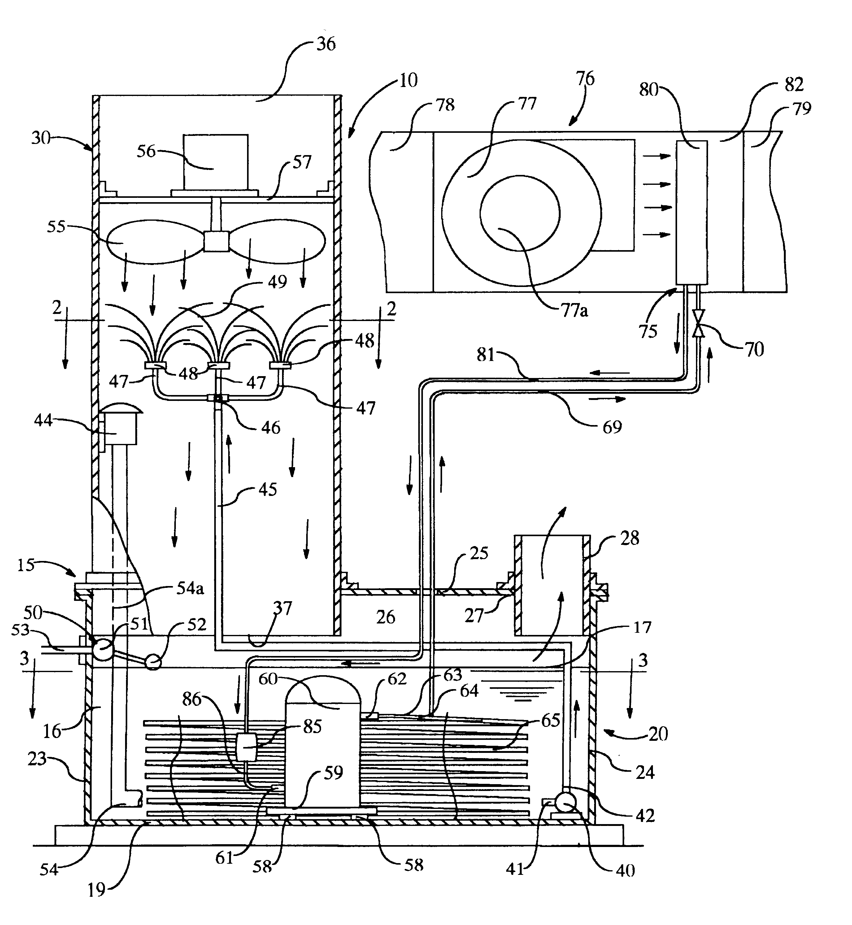
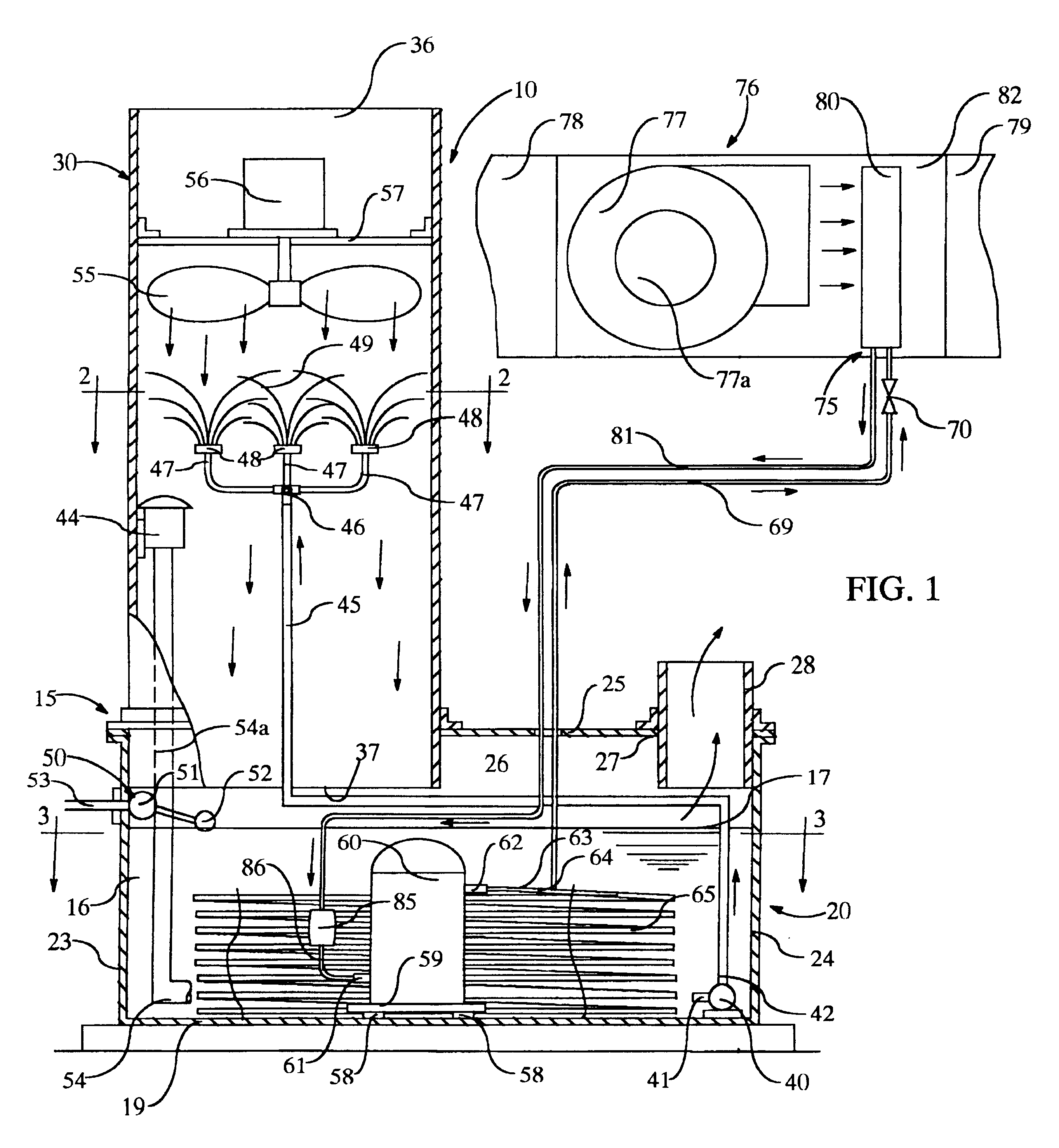
Referring to FIG. 1 of the drawing, the numeral 10 generally designates a water cooled air conditioner comprising a refrigerant condenser unit 15 and a refrigerant evaporator unit 75.

In the illustrated embodiment, the water cooled air conditioner 10 is a split system for residential central air conditioning, the refrigerant condenser unit 15 being located outside the building and the refrigerant evaporator unit 75 being located in an air handling unit 76, as will be hereinafter more fully described, located inside the building. However, it should be readily apparent that the refrigerant condenser unit 15 and the refrigerant evaporator unit 75 may be mounted in a single cabinet, if it is deemed expedient to do so, and the system is suitable for use in non-residential environments.

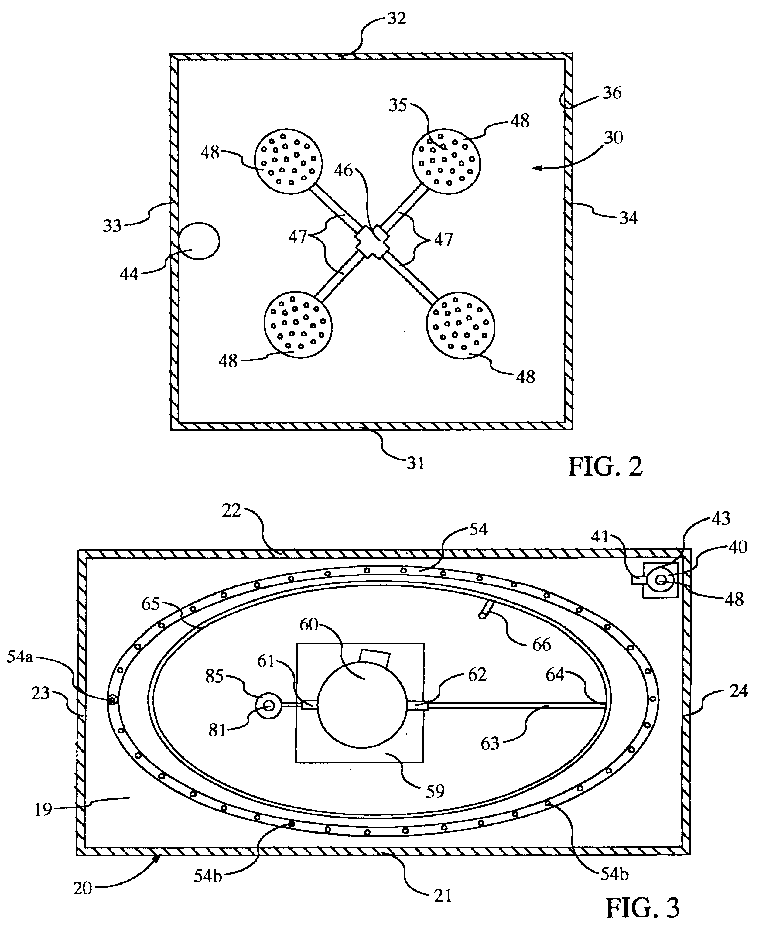
Referring to FIGS. 1 and 3 of the drawing, the refrigerant condenser unit 15 includes a water tank 20 and a water evaporation chamber 30. Water tank 20 comprises a front wall 21, rear wall 22, end walls 23 a...


PUM


Abstract

An air conditioner having a compressor, refrigerant condenser coil and accumulator submerged in water in a water tank, wherein the water is cooled by evaporative cooling when air is drawn through water sprayed into an air inlet duct communicating with the water tank. The compressor is cooled by the water in the water tank which is cooled by evaporative cooling. The water level in the water tank is maintained by a float valve connected to a water line to replenish evaporating water.

Description

An air conditioner having a compressor, condenser coil and accumulator submerged in a body of water in a water tank, wherein the water is cooled by evaporative cooling when air is circulated through a mist of water sprayed into a water evaporation chamber communicating with an air inlet into the water tank and through an air manifold in the tank.BACKGROUND OF INVENTIONVapor compression systems are employed in most refrigerated air conditioning systems. Cooling is accomplished by evaporation of a liquid refrigerant under reduced pressure and temperature. The refrigerant vapor enters the compressor where the temperature is elevated by mechanical compression. The vapor condenses at this pressure in a condenser coil, if sufficient heat is dissipated. The high-pressure liquid refrigerant then passes through an expansion valve where the fluid pressure is reduced. The low-pressure refrigerant enters the evaporator where it evaporates by absorbing heat from the refrigerated space, and reent...

Claims


Application Information

Patent Timeline
Patent Type & Authority Patents(United States)
IPC IPC(8): F25B39/04F24F5/00F24F13/22F24F13/00
CPCF24F5/0035F25B39/04F24F2013/225F25B2339/041F25B2339/047Y02B30/545Y02B30/54
Inventor FORGY, CHARLES L.
Owner CHANEY LINDA FORGY
Why Eureka
Try Eureka