Fluid level sensing and control system

a control system and fluid level technology, applied in liquid/fluent solid measurement, machines/engines, instruments, etc., can solve the problems of manual corrective function, many problems with these mechanisms, and inability to accurately detect the level of fluid, etc., to minimize the system cost, reliable, affordable and easy-to-use effects

Inactive Publication Date: 2003-07-22
SJE RHOMBUS
View PDF12 Cites 78 Cited by
  • Summary
  • Abstract
  • Description
  • Claims
  • Application Information

AI Technical Summary

Benefits of technology

In one exemplary embodiment of the present invention, a plurality of microswitches are housed in a head portion of the housing, at a second or upper housing end. The microswitches are each adjustably and removably connected on a switch track assembly such that each one is tripped at a different plunger vertical elevation within the housing, thereby allowing for adjustable fluid level control within the vessel.
In one exemplary embodiment, the switch track assembly comprises a top piece and a bottom piece connected by four identical spaced switch mounting rails, or switch track rods. The microswitches are each connected to a switch coupler piece that snaps onto an adjacent pair of the rods, such that the switch trigger can be contacted by the plunger coming through a hole in the bottom piece of the switch track assembly in response to sensed fluid pressure on the overall piston assembly. Each switch coupler and corresponding microswitch pair can easily be snapped along the switch track rails making for an adjustable fluid level control system. In an alternative embodiment, the switch track assembly can accommodate up to fourteen such commercially available microswitches each mounted on a removable switch coupler to two adjacent switch track rods.
Although one surface of the rolling diaphragm is meant to be continuously exposed to fluid material in the tank at a subsurface fluid level, the remaining interior of the housing is sealed from the fluid and can be connected to a source of fresh air, such as by a vent tube or line connected at some upper apparatus location to outside air external to the fluid vessel. In this way, the switches are not exposed to corrosive liquids or gases within the vessel and the volume of air displaced by the rolling diaphragm and piston assembly in response to a fluid elevation increase in the vessel can be vented. Correspondingly, the vent line serves as a source of fresh air brought into the apparatus when the fluid elevation within the vessel is decreased, such as by a pump discharge cycle, and the rolling diaphragm unrolls or relaxes with the piston assembly moving downward.
In exemplary embodiments

Problems solved by technology

Visual readings, however, are often not desirable, in systems where an automatic response is required when the fluid level reaches a certain threshold.
Unfortunately having a human operator manually initiate a corrective function may not be desirable due to the repetitive nature of the function or due to the inefficiency of having a human operator in the system.
Unfortunately, numerous problems have been encountered with these mechanisms.
For example, turbulent conditions within a fluid-holding vessel can negatively impact performance of float switch systems.
Such turbulence is often the result of fluidized material inflow and/or pump-discharged fluid material exiting the tank.
This turbulence can create undesirable eddies and waves within the tank that can cause tethered tilt style float switches to become entangled, thus preventing them and the system from proper operation.
In addition, the turbulence within the tank can cause inadvertent switching and what is often referred to as "contact chatter" of the switches within the tilt style float switch assemblies.
Inadvertent switching can cause system inefficiency and degradation, such as a false level reading which causes a pump to turn on or off earlier or later than desired.
Such contact chatter can cause the pump, which is responsive to the triggered switch, to cycle inadvertentl

Method used


Image

  • Fluid level sensing and control system
  • Fluid level sensing and control system
  • Fluid level sensing and control system

Examples


Embodiment Construction

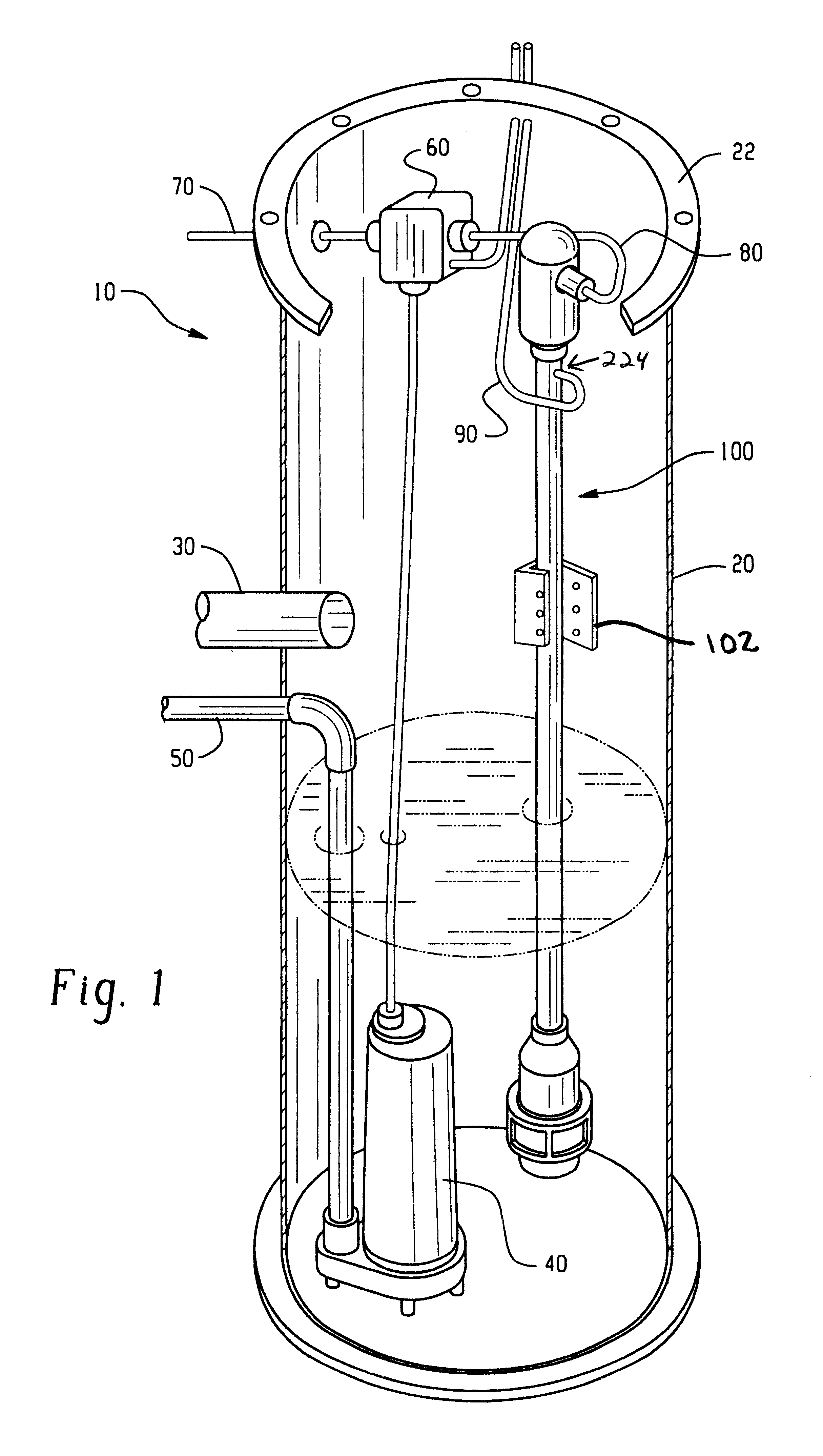
Referring now to the figures, which are for the purposes of illustrating the present invention and not for limiting same, FIG. I depicts a liquid level control system 10 in accordance with an exemplary embodiment and the principles of the present invention. Included are a fluid-holding vessel 20, a fluid inlet line 30 for bringing fluidized material into vessel 20, a fluid pump 40 for discharging fluid material from vessel 20 via a discharge line 50, a typical junction box 60 having a power cord 70 for connecting with a power source (not shown), a switch cord 80, which can be any suitable length for connecting the pressure activated control apparatus, shown generally at 100, with the junction box 60, and a vent line 90 for venting air from within the pressure activated control 100 and as a source of fresh outside air thereto. The flange 22 radially extending outwardly from around the top of vessel 20 can be connected with a vessel lid (not shown) to make an enclosed fluid vessel. In...


PUM


Abstract

An improved pressure activated control apparatus is provided for sensing fluid pressure and triggering one or more switches in response to the fluid pressure, as desired. The apparatus is designed to be placed within a fluid of a reservoir. The apparatus includes a first resilient member, such as a pliable rolling diaphragm or bellofram, having an outer surface exposed to the fluid and responsive to the fluid pressure. The pressure activated control apparatus includes a second resilient member, such as a spring with a chosen spring constant, k, that provides a biasing force against the diaphragm that is opposite the fluid pressure. A transducer is operative to monitor changes in pressure of gases within the apparatus causes by movement of the diaphragm. A controller is responsive to the transducer and selectable fluid level thresholds to activate pumps and/or valves for adjusting the level of the fluid in the reservoir.

Description

The present invention relates to pressure-responsive systems and components. Specifically this invention relates to devices and systems that sense the level or depth of fluids and responds thereto by triggering switching mechanisms.It is often desirable to know information about fluid levels in tanks. Determining fluid levels and controlling fluid levels in tanks, such as in sewage tanks, water cisterns or tanks, and other fluid system and storage vessels, whether enclosed or open and exposed to the environment, has been done in a number of ways. For example, in tanks that are visually accessible, an operator may periodically take visual readings of the fluid level.Visual readings, however, are often not desirable, in systems where an automatic response is required when the fluid level reaches a certain threshold. In such cases the activation of a pump or valve may be necessary to move more fluid into the vessel or to discharge fluid from the vessel. In systems where visual readings...

Claims


Application Information

Patent Timeline
IPC IPC(8): G01F23/14G01F23/18G01F23/16H01H35/18
CPCG01F23/161G01F23/185H01H35/18H01H35/2628H01H35/2657
Inventor CHANDLER, JR., WILLIAM D.
Owner SJE RHOMBUS
Why Eureka
Try Eureka