Internal combustion engine

a combustion engine and internal combustion technology, applied in the direction of machines/engines, output power, electric control, etc., can solve the problems of inability to completely empty the cylinder, inability to supply new air to the cylinder, poor volumetric efficiency, etc., to increase the mass flow of exhaust gases, increase torque, and increase the effect of charging pressur

Inactive Publication Date: 2003-07-22
SAAB AUTOMOBILE AB
View PDF10 Cites 97 Cited by
  • Summary
  • Abstract
  • Description
  • Claims
  • Application Information

AI Technical Summary

Benefits of technology

By means of the chosen embodiment, it is possible to control the gas flow through the engine so that exhaust gases are allowed out without an unnecessarily great quantity of air fed in being able to "leak out" via an exhaust valve which is still open. This leads to more effective filling of the cylinder and as a result an increased mass flow of exhaust gases, which in turn increases the possibility of increasing the torque at low engine speed by means of a higher charging pressure.
The synchronization between the valves can advantageously be such that, as the engine speed increases, the intake valve opens increasingly early before the top dead centre position of the piston while the second exhaust valve closes increasingly late after the top dead centre position of the piston. In this way, the position of maximum opening can be reached when the piston is at or very close to the top dead centre position.

Problems solved by technology

At full throttle, however, poor volumetric efficiency is obtained as a consequence of a negative pressure difference between the inlet and the outlet during the period in which inlet valves and exhaust valves are open at the same time.
This means that it is not possible to empty the cylinder completely during the exhaust stroke, as a result of which the desired quantity of new air cannot be supplied to the cylinder either.
Another consequence is that the exhaust flow at low engine speed is insufficient to drive the turbine effectively, with the result that the charging pressure is not optimal.
The result is an imbalance in the mass flow between the compressor and the turbine, which results in the turbine not being capable of making the compressor deliver sufficient charging pressure.
This in turn results in the torque being impaired.
On the other hand, if the valve overlap is too small, residual gases will remain in the cylinder, with the result that the quantity of combustion air is reduced with the attendant reduction in power.

Method used


Image

  • Internal combustion engine
  • Internal combustion engine
  • Internal combustion engine

Examples


Embodiment Construction

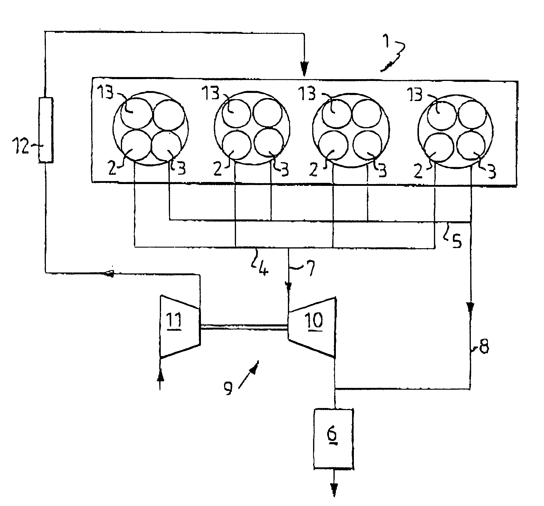
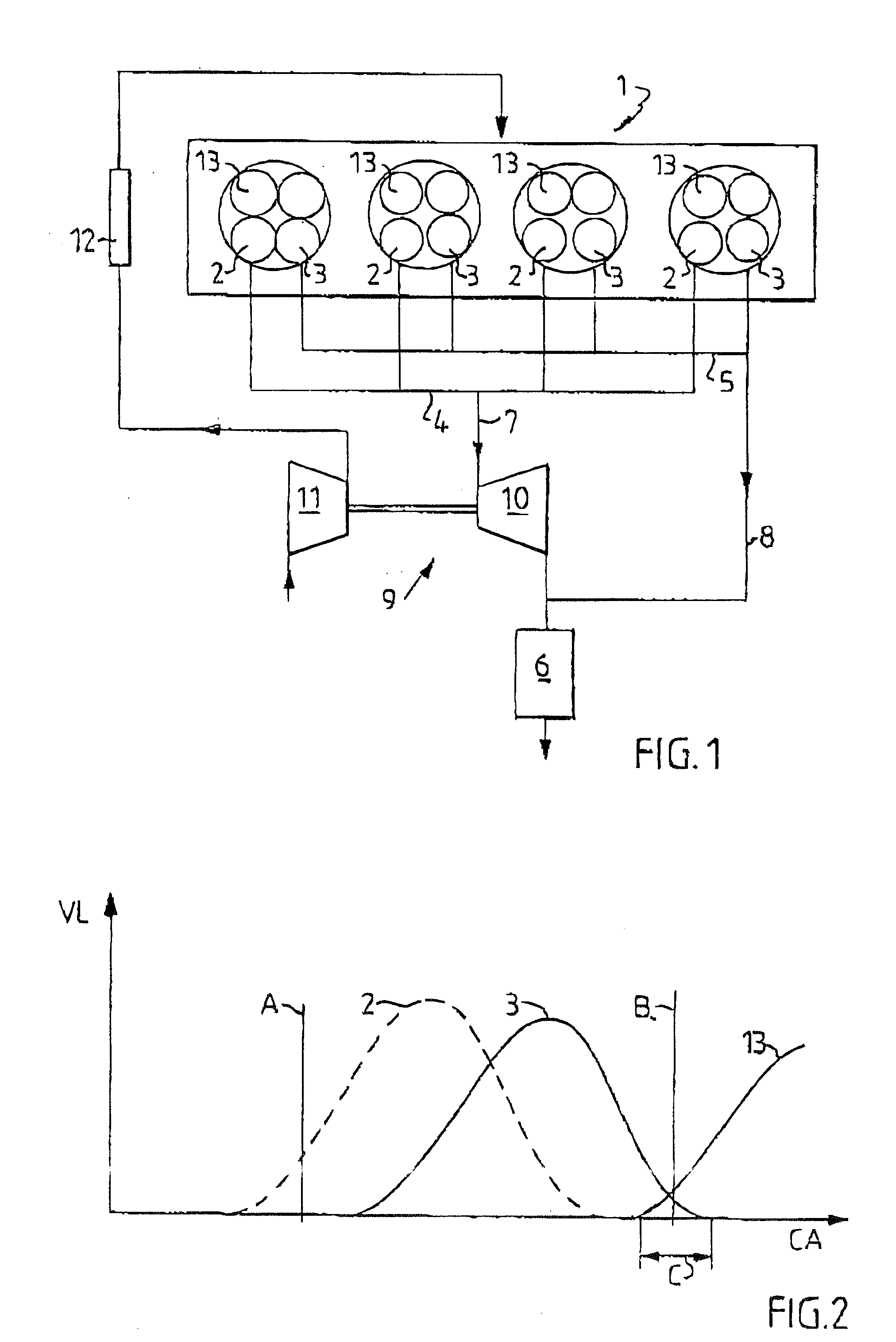
FIG. 1 shows diagrammatically a multicylinder internal combustion engine 1 according to the invention embodied as an Otto engine. The cylinders of the engine each have at least two exhaust valves 2 and 3. Exhaust is conducted out from the first exhaust valves 2 of the cylinders to a first exhaust manifold 4 common to the cylinders. Exhaust is conducted out from the second exhaust valves 3 of the cylinders to a second exhaust manifold 5 common to the cylinders. The first exhaust manifold 4 is connected to a catalyst 6 via a first exhaust line 7, and the second exhaust manifold 5 is connected to the catalyst 6 via a second exhaust line 8. One or more silencers (not shown) is or are located downstream of the catalyst 6 in a conventional manner.

The engine 1 is also equipped for supercharging by means of an exhaust-driven turbocompressor 9 (or turbocharger), the turbine 10 of which is connected in the first exhaust line 7 and is therefore fed from the first exhaust manifold 4 and the fir...


PUM


Abstract

A multicylinder internal combustion engine with an exhaust-driven turbocompressor and with a divided exhaust flow has at least two exhaust valves and one intake valve per cylinder. A first exhaust valve is connected to a first exhaust manifold which leads to the turbine of the compressor, while a second exhaust valve is connected to a second exhaust manifold which opens downstream of the turbine. In the top dead center position of the piston, the second exhaust valve and the intake valve are open at the same time for a period. The synchronization between these valves is such that the length of the period during which they are open together increases with the engine speed when the engine is driven at high load. In this way, the possibilities are improved of the engine providing good torque over a wide engine speed range.

Description

The invention relates to an internal combustion engine, particularly a supercharged engine, with a divided exhaust flow and particularly relates to control over the operation of the intake and exhaust valves to the cylinders.STATE OF THE ARTThe use of turbocharged engines, that is to say engines in which supercharging is carried out by means of a compressor which is driven by an exhaust-driven turbine, is becoming increasingly common within automotive technology. At high power, a greater charge can as a result be utilized than in a conventional engine. At full throttle, however, poor volumetric efficiency is obtained as a consequence of a negative pressure difference between the inlet and the outlet during the period in which inlet valves and exhaust valves are open at the same time. This means that it is not possible to empty the cylinder completely during the exhaust stroke, as a result of which the desired quantity of new air cannot be supplied to the cylinder either. Another con...

Claims


Application Information

Patent Timeline
Patent Type & Authority Patents(United States)
IPC IPC(8): F02F1/42F02D13/02F02B37/18F01L1/34F02B37/00F02B37/02F02D23/00F02D41/02F02D41/04
CPCF01L1/34F02B37/02F02B37/18F02D13/0203F02D13/0249F02D13/0257F02D13/0261F02F1/4214Y02T10/18Y02T10/144Y02T10/12
Inventor OLOFSSON, ERIC
Owner SAAB AUTOMOBILE AB
Why Eureka
Try Eureka