Roller bit parallel inlayed compacts

a technology of compacts and rollers, applied in the field of rollers, can solve the problems of steel-teeths that are easy to wear, lose cutting function, steel-teeth still cracks or breaks, etc., and achieve the effect of low cost and easy machine operation

Inactive Publication Date: 2003-07-22
KINGDREAM PLC CO
View PDF34 Cites 8 Cited by
  • Summary
  • Abstract
  • Description
  • Claims
  • Application Information

AI Technical Summary

Benefits of technology

The object of this invention is to overcome the above problems and to provide a roller bit with parallel compacts which are easy to machine, but also low cost, and can drill through earth formation with stringers effectively.
The invention has the following advantages: 1. By employing parallel compacts, the cutting performance is similar to that of oblate compacts which have longer cutting edges. The noncontinuous long crest of compacts according to the invention are constructed so that it is easy to engage an earth formation and is thus helpful in improving rock breaking efficiency and the life of the bit. In addition, the teeth-groove and the annular separating groove create an advantage for chip removing, improvement of the cutting condition, and preventing bit balling; 2. By adopting a cylindrical body, it is not only easier to machine, but also creates high fitting precision, so that product quality can be guaranteed with low manufacture costs and good economy; 3. The roller bit according to the invention can drill through hard earth formations, and also break the hard earth formation with a scraping action, so it is effectively applied to earth formations with stringers, therefore increasing drilling efficiency.

Problems solved by technology

The teeth and the cone of the steel-teeth bit are integrally formed, with a broad tooth cutting edge which can effectively scrape and chisel the soft earth formation, but when a hard formation is reached, the steel-teeth are easily worn with the result of losing their cutting function.
Even when coated with an abrasion-resistant material, the steel-teeth still crack or break when they encounter hard formations.
The compacts of this kind of bit are usually made from carbide, with higher hardness which are more wear-resistant, but the cutting edge of the compact not as broad as in the steel tooth bit and cannot effectively drill into a soft formation.
From this we can see that the prior art steel teeth bit and compact bit both cannot be effectively applied for use on a formation with stringers.
The manufacture of such a roller bit and oblate compact is difficult, inefficient and not cost effective.

Method used


Image

  • Roller bit parallel inlayed compacts
  • Roller bit parallel inlayed compacts
  • Roller bit parallel inlayed compacts

Examples


second embodiment

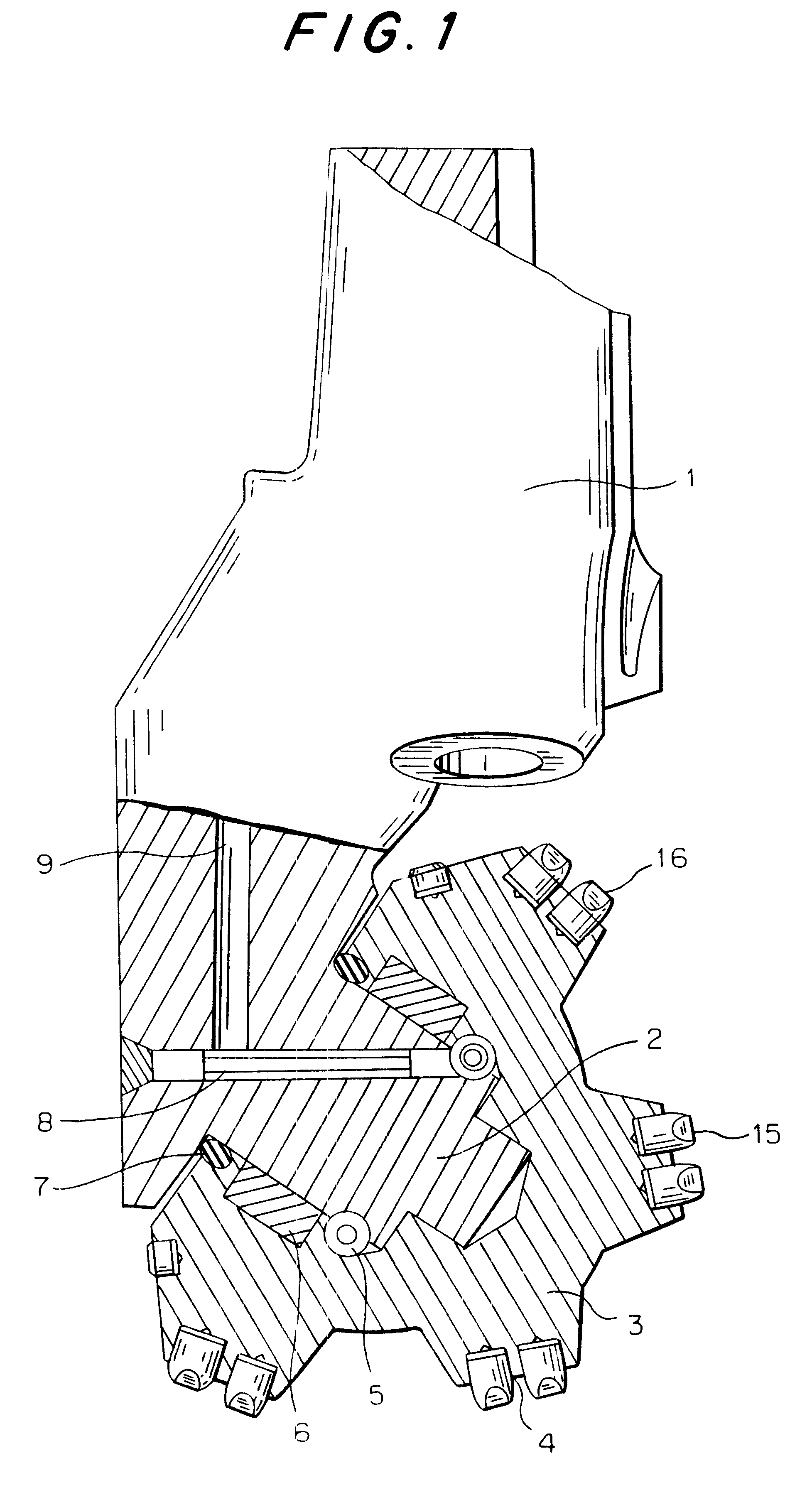
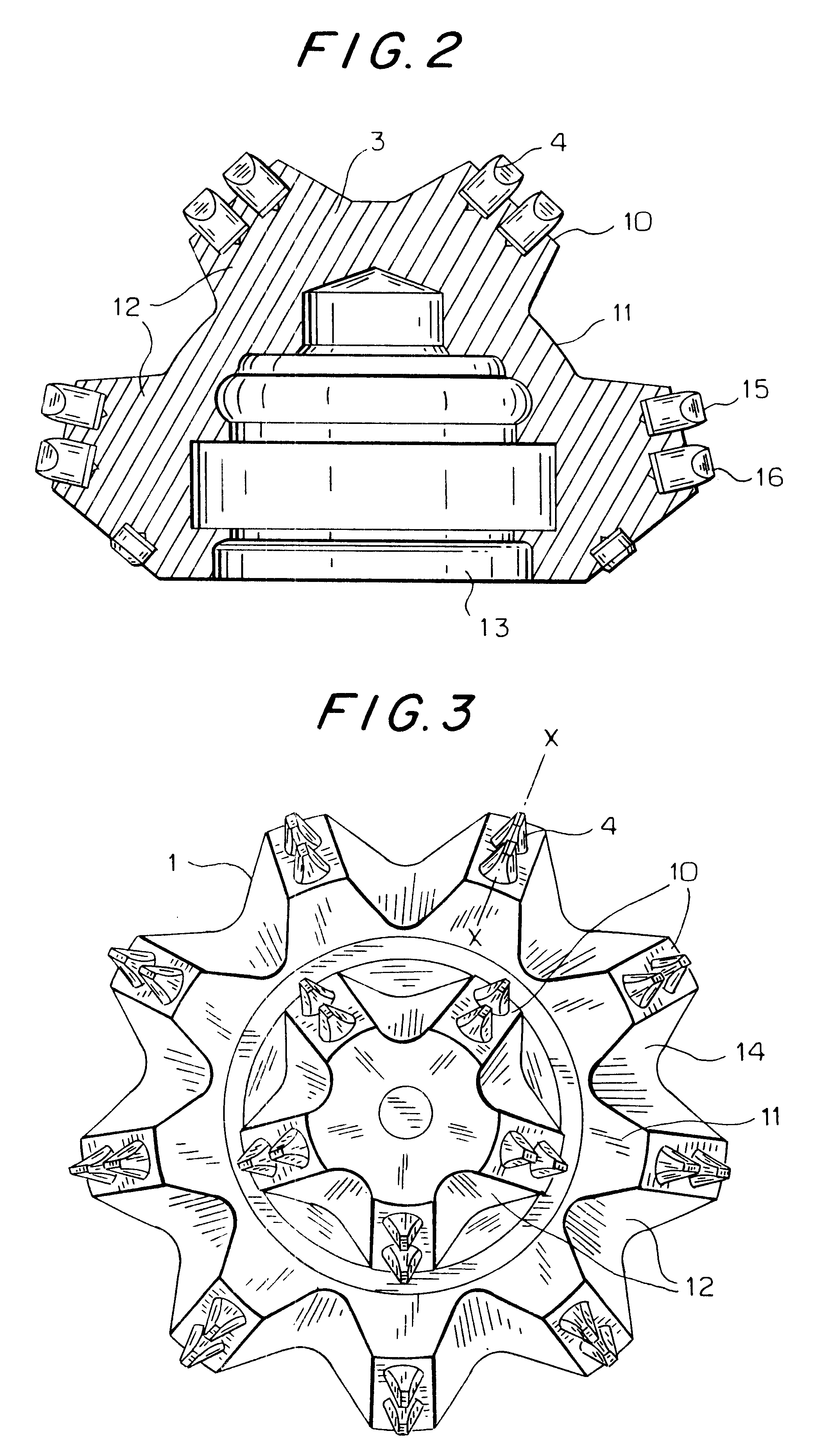
this invention is shown in FIG. 4. The main difference from the embodiment of FIGS. 2 and 3 is that the longitudinal direction of the base teeth 14 biases at an angle relative to the generatrix y-y of the cone body so that the base teeth 14 have a spiral taper having a spiral angle .alpha. of between 5-15 degrees between the generatrix of the cone. There are two layers or sets of compact lands 10 arranged on the cone 3 as in the embodiment FIGS. 2 and 3, and four compact land layers or sets can be formed if desired. Two compacts 4 are parallelly arranged at the top of the base teeth 14 in the upper compact land along the longitudinal direction of the land, and three compacts are parallelly arranged at the top of the base teeth 14 in the lower compact land along the longitudinal direction of the land. The annular separating grooves 11 are arranged between the compact lands, and the teeth-grooves 12 are made on each of the compact land.


PUM


Abstract

This invention relates to a roller bit applying for the oil, natural gas, mine and geological drilling, and more particularly relates to a kind of roller bit with the parallel inlayed compacts, it includes head and cone, the compact land and the teeth-groove are arranged on the cone, the difference is that there are 2 to 3 compacts having the cylindrical body being arranged on the top of the base teeth along the teeth direction.The cutting performance of the present invention is similar to that of the oblate compacts, and, by utilizing the conventional cylindrical compacts, it is not only easy to process and with low manufacturing cost, but the bit can effectively drill through the stringered earth formation with both hard and soft formation and thus better economic benefit from drilling the stringered formation can be obtained.

Description

1. Technical Field of the InventionThis invention relates to a roller bit for use in drilling for the oil, natural gas, mine and geological drilling, and more particularly relates to a roller bit with the parallel inlayed compacts.2. Prior ArtRoller bits have been widely used as a tool for earth boring. A roller bit usually consists of the cone and the head. The cone may be one or more, and the head is moveably attached an inner hole of the cone by a suspending-arm shaft at the lower part of the head, so that the cone can rotate around the shaft. The cutting structure of the outer surface of the cone crushes the rock formation under the action of the impact and the slide shearing generated by the combined movement of the cutting structure with revolution, self-rotation and the axial advancement of the cone.The prior art roller bits are divided into two sorts which are a steel-tooth bit and a compact bit. The teeth and the cone of the steel-teeth bit are integrally formed, with a bro...

Claims


Application Information

Patent Timeline
Patent Type & Authority Patents(United States)
IPC IPC(8): E21B10/46E21B10/16E21B10/52E21B10/08
CPCE21B10/16E21B10/52
Inventor CHEN, ZHIHUA
Owner KINGDREAM PLC CO
Why Eureka
Try Eureka