

Un-reinforced thermoplastic coating
a thermoplastic coating and unreinforced technology, applied in the direction of synthetic resin layered products, transportation and packaging, wood layered products, etc., can solve the problems of uneven swelling stress, paint system breakdown, and quick breakdown of the coating system
- Summary
- Abstract
- Description
- Claims
- Application Information
AI Technical Summary
Problems solved by technology
Method used
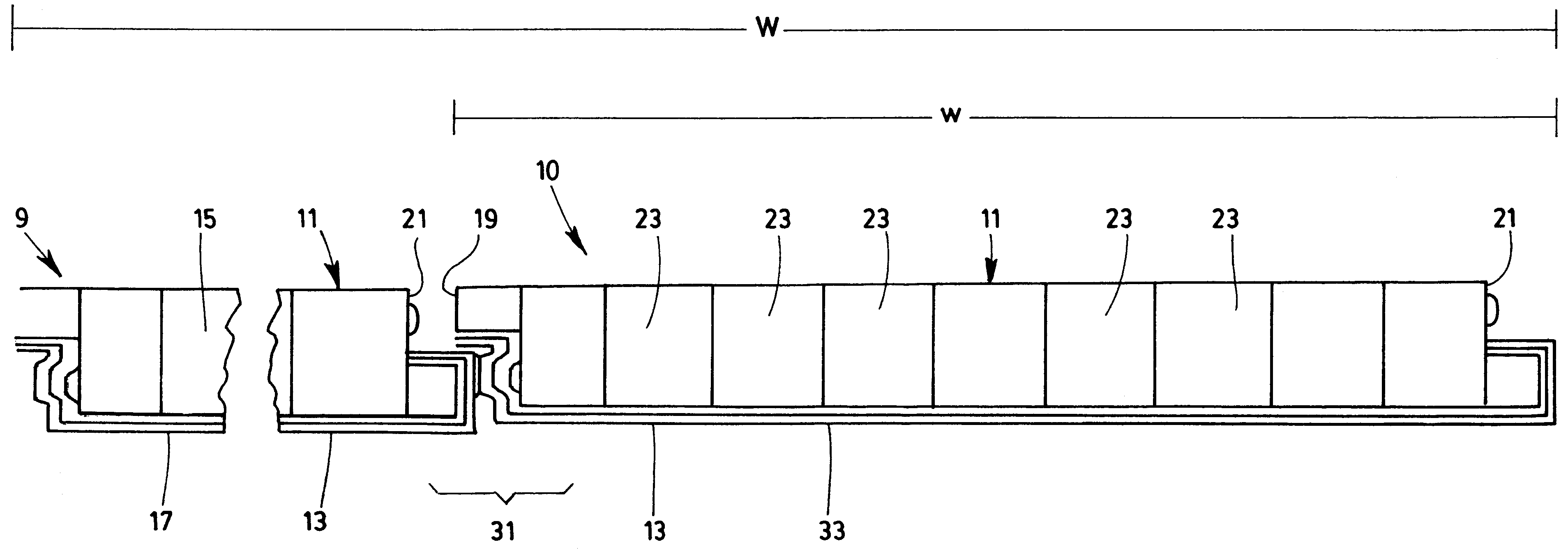
Image

Examples
Embodiment Construction
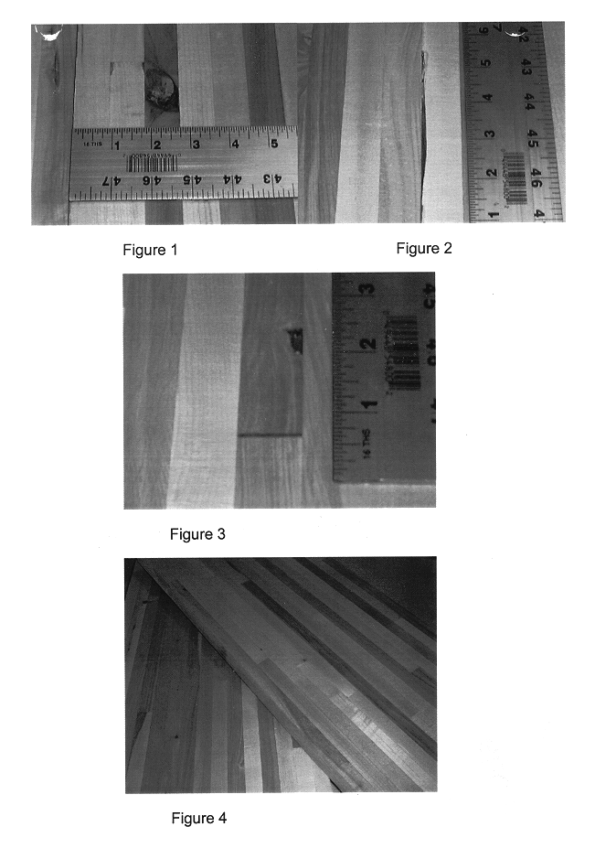
In order to aid in comprehending the context of the present invention, reference will be made to the figures in order to illustrate some of the issues raised in the background of the invention.
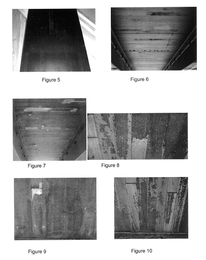
FIG. 1 is a photograph of average knot defect in a wood floor. FIG. 2 is a photograph of the average split seam defect in wood floor at the glue line location. FIG. 3 is a photograph of hook joint gap defect in wood flooring. FIG. 4 is a photograph of completed wood boards with defects repaired and prepared for painting. FIG. 5 is a photograph of wood plank which has been painted according to the prior art and ready for installation. FIG. 6 is a photograph of an installed wood flooring on a truck chassis (note visible defect repairs in paint). FIG. 7 is a photograph of a truck floor undercoat paint peeling after 1 year of service; where FIG. 8 is a photograph of a truck floor undercoat paint showing near complete degradation after 1.5 years of service. Note the accentuated hook joint and split...
PUM
| Property | Measurement | Unit |
|---|---|---|
| elongation | aaaaa | aaaaa |
| length | aaaaa | aaaaa |
| length | aaaaa | aaaaa |
Abstract
Description
Claims
Application Information