Low maintenance cutting rubber

a cutting rubber, low-maintenance technology, applied in the direction of band saws, manufacturing tools, transportation and packaging, etc., can solve the problems of affecting the quality of cutting rubber, and requiring considerable down time for the press to maintain the exchange of anvil bars on cutting cylinders, etc., to achieve the effect of easy replacement of the entire bel

Inactive Publication Date: 2003-08-12
SHANGHAI ELECTRICGROUP CORP
View PDF22 Cites 28 Cited by
  • Summary
  • Abstract
  • Description
  • Claims
  • Application Information

AI Technical Summary

Benefits of technology

The present invention offers the advantage to index said belt upon wear of the cut rubber spot to a fresh cut rubber spot or portion, respectively. When there are no more fresh spots, the entire belt can be replaced very easily. Furthermore, a constraint is exerted upon the incoming web and the signature resulting there from over the entire length of the cutting region, prior to the cutting region and behind the cutting region.
According to further details of the present invention, said transport belt travels along an endless loop about said supporting element which may be designed as an anvil cut roller or cylinder with a smooth surface. Sai

Problems solved by technology

Maintenance regarding the exchange of anvil bars on cutting cylinders requires considerable down time of the press.
Further, the accessibility of said anvil bars is difficult.
A further dis

Method used


Image

  • Low maintenance cutting rubber
  • Low maintenance cutting rubber
  • Low maintenance cutting rubber

Examples


Embodiment Construction

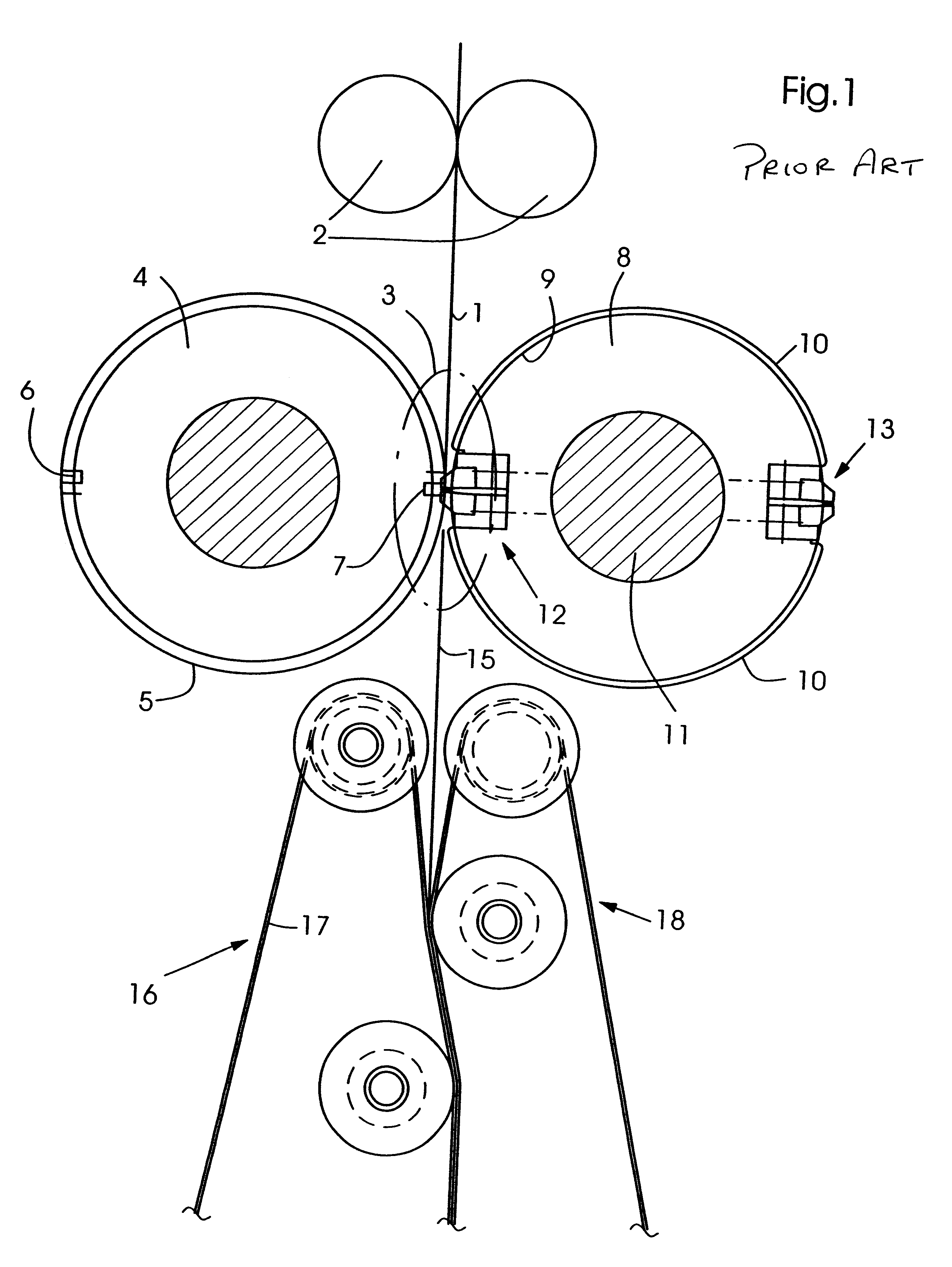
FIG. 1 shows an existing cutting cylinder pair design with the anvil cylinder having anvil bars assigned thereto.

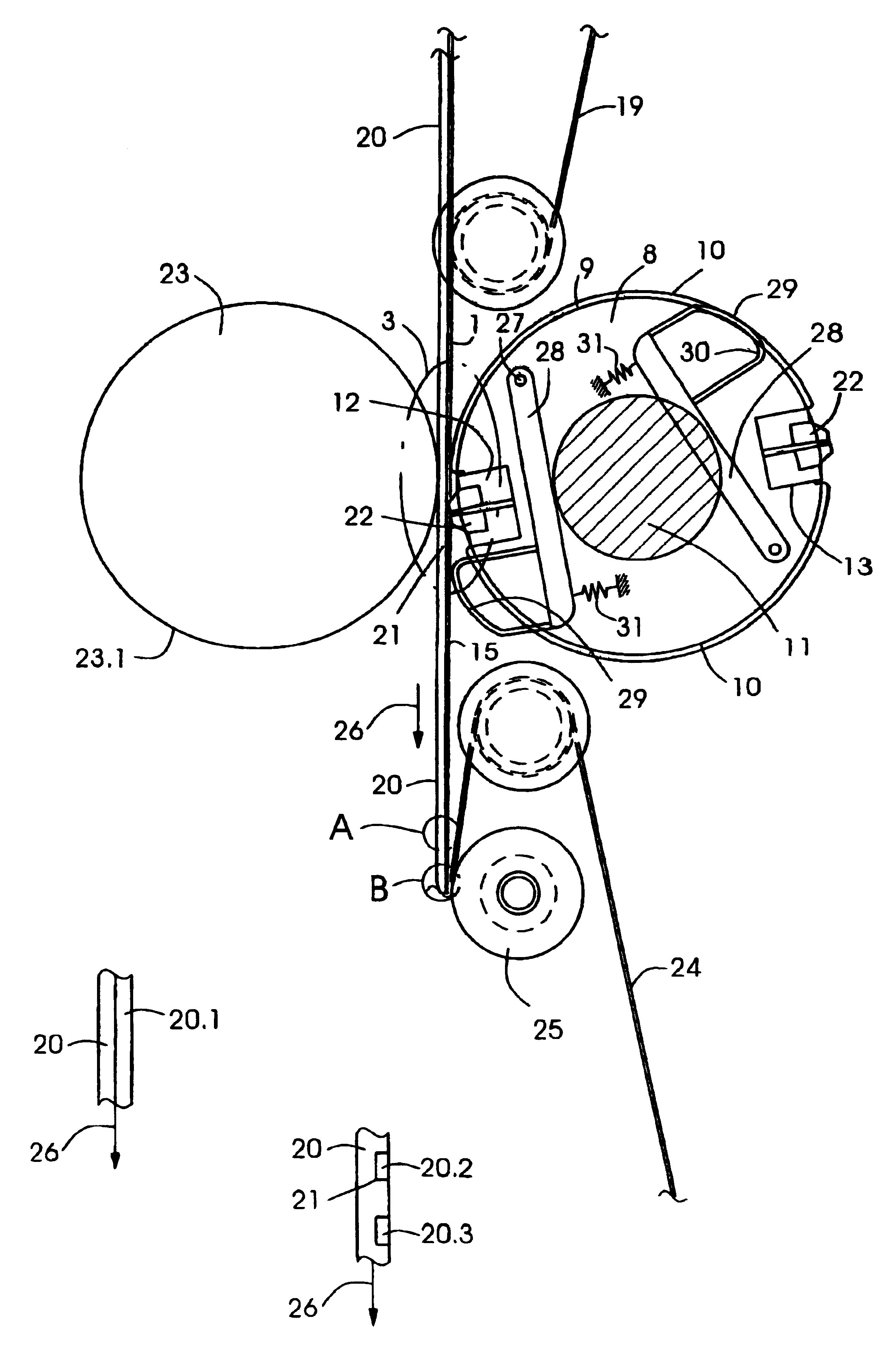
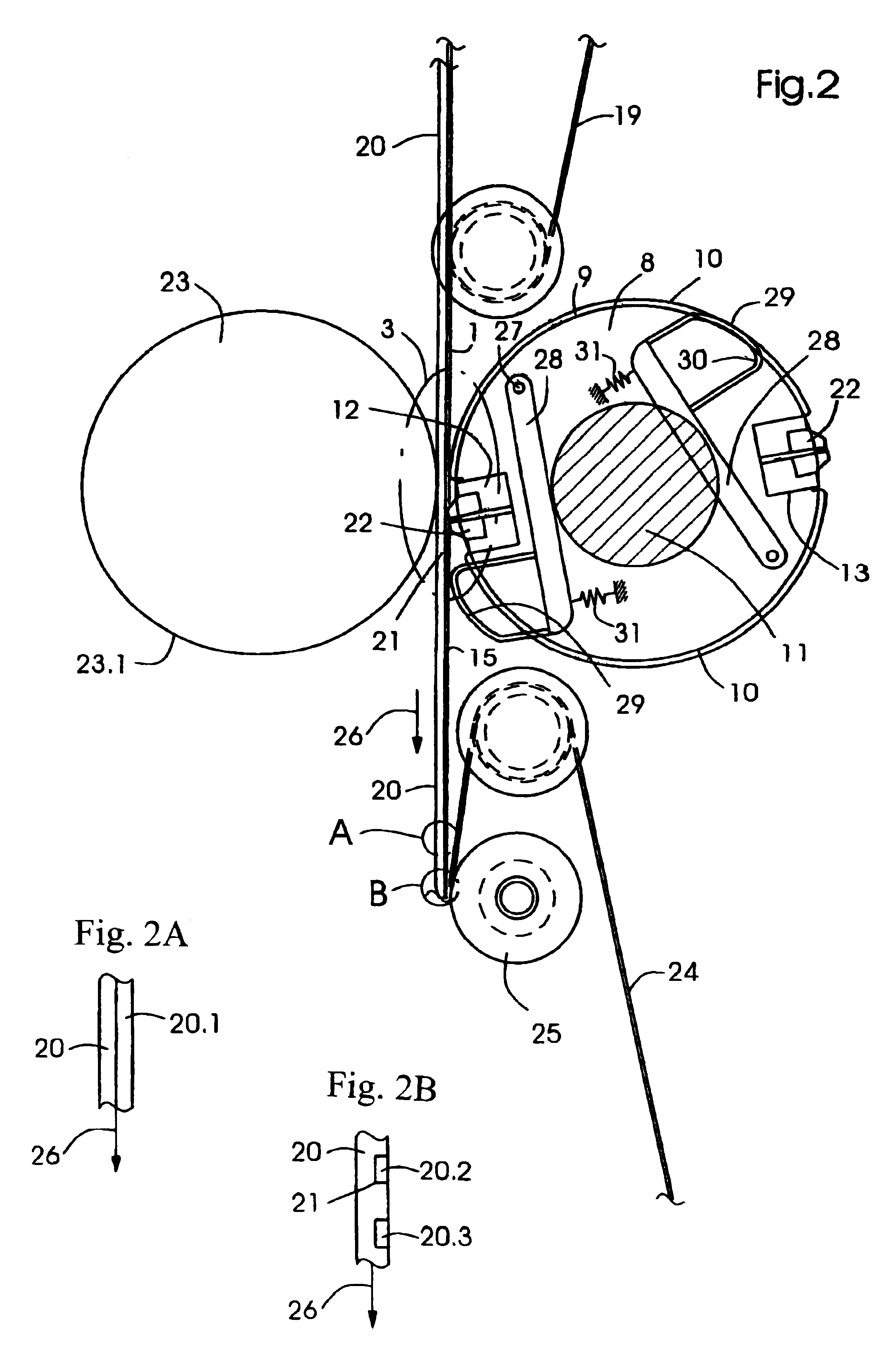
An incoming web of material 1 is forwarded into a cutting region 3 by a pair of nip rollers 2 arranged above a cutting cylinder pair, including an anvil cylinder 4 and a knife cylinder 8. Knife cylinder 8 includes two knife assemblies, a first knife assembly 12 and a second knife assembly 13. Between said first and second knife assembly 12, 13, respectively, surface jackets 10 are assigned to the circumference 9 of said knife cylinder 8. Said first and second knife cylinder assemblies 12, 13, respectively, are arranged opposite to one another, thus severing two signatures from the incoming web of material 1 upon a complete revolution. Said anvil cylinder 4 has two rectangularly shaped anvil bars, a first anvil bar 6 and a second anvil bar 7 cooperating with said first and second knife assemblies 12, 13 respectively, of said knife cylinder 8. Said first and second anvil ba...


PUM

PropertyMeasurementUnit
Lengthaaaaaaaaaa
Widthaaaaaaaaaa
Distanceaaaaaaaaaa

Abstract

The present invention is related to an apparatus for cutting webs of material (1) and includes a cutting cylinder (8) having at least one knife assembly (12, 13) assigned to its circumference (9). A supporting element (23) is assigned to said cutting cylinder (8) forming a cutting region (3) there between and a transport belt (20) having cut rubber portions (20.1, 20.2, 20.3) integrated therein is assigned to said supporting element (23).

Description

FIELD OF THE INVENTIONThe present invention is related to a cutting rubber assembly which requires low maintenance and which can be used in machines that cut webs of any sort.BACKGROUND OF THE INVENTIONU.S. Pat. No. 5,107,733 is related to an apparatus for cutting and transporting a paper web in a folding apparatus of a printing press. An apparatus for transporting a web in a printing press comprises a pair of cutting cylinders for cutting web sections from the web, and a transporting device for transporting the web sections away from the cutting cylinders. The first cutting cylinder has at least one cutting angle and the second cutting cylinder has at least one cutting knife which meets the cutting angle at a nip between the cutting cylinders, to cut the web moving through the nip. A plurality of strips are supported on the first cutting cylinder and a plurality of strips are supported on the second cutting cylinder. The strips have positioned on the cutting cylinders in which they...

Claims


Application Information

Patent Timeline
IPC IPC(8): B26D1/62B26D1/00B26D7/20B26D7/08B26D7/00B65H35/08B65H35/04B65H35/06B65H45/28
CPCB26D1/626B26D7/08B26D7/20B65H35/08B26D2007/082Y10T83/2192Y10T83/4841Y10T83/2109Y10T83/4795Y10T83/6633
Inventor BELANGER, JAMES RICHARDCOTE, KEVIN LAUREN
Owner SHANGHAI ELECTRICGROUP CORP
Why Eureka
Try Eureka