Process and apparatus for making multi-layered, multi-component filaments

a multi-component, process and apparatus technology, applied in the direction of melt spinning methods, applications, manufacturing tools, etc., can solve the problems of significant number of spinneret orifices, non-uniform filament production of hole dies, and reducing the capacity for downstream filtering, so as to reduce or eliminate unwanted particulate passing

Inactive Publication Date: 2003-08-12
3M INNOVATIVE PROPERTIES CO
View PDF16 Cites 11 Cited by
  • Summary
  • Abstract
  • Description
  • Claims
  • Application Information

AI Technical Summary

Benefits of technology

The polymers are melted into separate molten polymer flow streams using conventional means, such as extruders, and forced through separate distribution manifolds to produce separate planar molten polymer flow streams. The distribution manifolds arrange the molten polymer flow streams into long thin planes of molten polymer, wherein the polymer all along the plane has nearly the same heat history and residence time. It is optimal for the molten polymer stream to have as much as possible the same heat history and residence time in order to minimize degradation of the polymer contacting the manifold walls, which tends to form solidified particles which can plug the spinneret orifices downstream, and / or form less uniform spun filaments. A common distribution manifold is a coat hanger manifold, which is named as such due to its general resemblance (in longitudinal cross section) in form to a coat hanger. Due to the long, thin form of the coat hanger distribution manifold, heat from the walls of the melt spinning beam is transferred through the molten polymer almost instantaneously, thus minimizing heat gradients within the spin beam and reducing non-uniform heating of the polymer.
In spite of the use of coat hanger distribution manifolds, the molten polymer within the spinning beam is invariably somewhat degraded at the interface with the walls of the spinning beam, both within the coat hanger manifold and in the inlet passages to the spinning beam. Accordingly, in the present invention, the planar molten polymer flow streams are individually filtered prior to being combined, but downstream of the coat hanger distribution manifolds, greatly reducing or eliminating unwanted particulate passing into the spinneret which might plug the spinneret exit orifices. In this manner, each of the multiple molten polymer streams can be filtered, without causing upsets in flow after combination of the streams, which would adversely affect the layered natures of the streams and therefore the resulting filaments.

Problems solved by technology

Unfortunately, this eliminates the capacity for downstream filtering as filtering of the bicomponent melt stream would cause mixing of the layered polymer streams.
Unfortunately, this split hole die can produce non-uniform filaments.
In systems where the polymers are not filtered, there are a significant number of spinneret orifices that plug during the start-up of the die and during operation, as the orifices are not protected from particles that come through the melt system.

Method used


Image

  • Process and apparatus for making multi-layered, multi-component filaments
  • Process and apparatus for making multi-layered, multi-component filaments

Examples


example 1

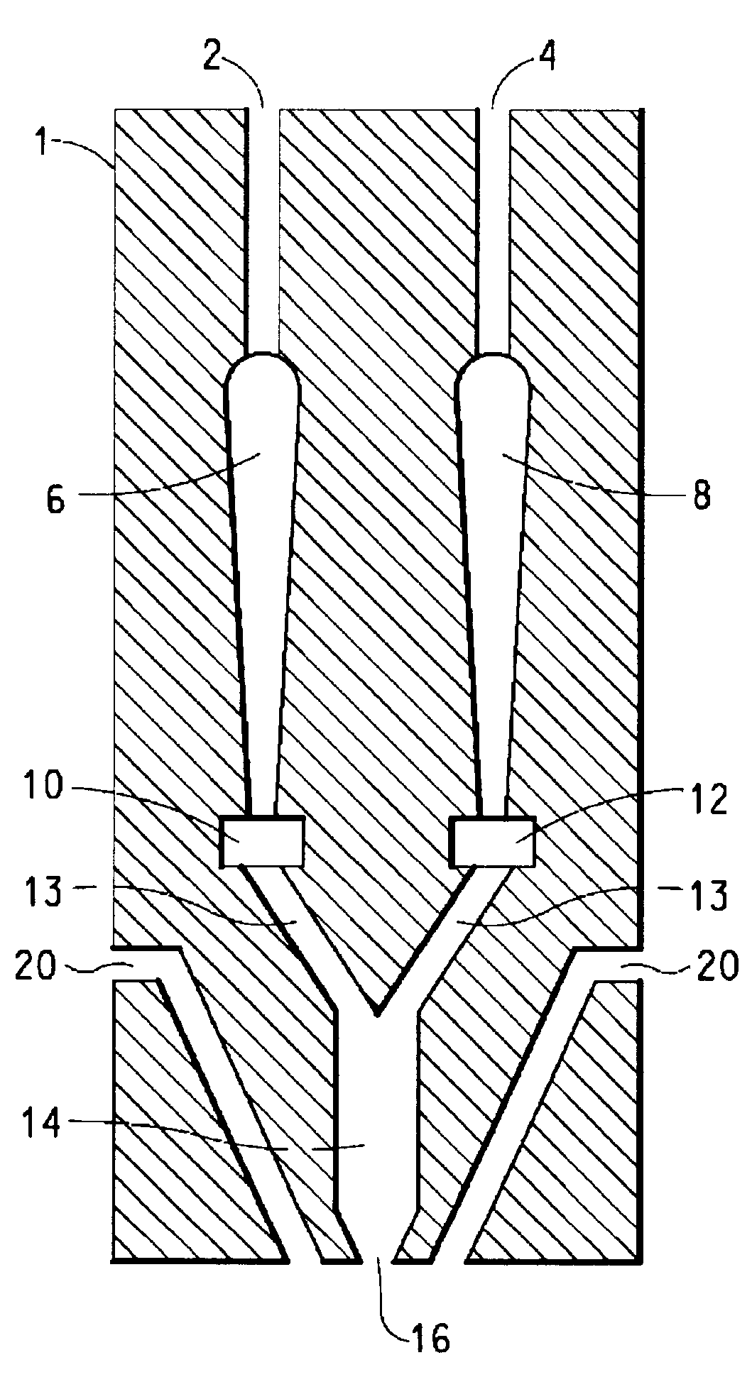
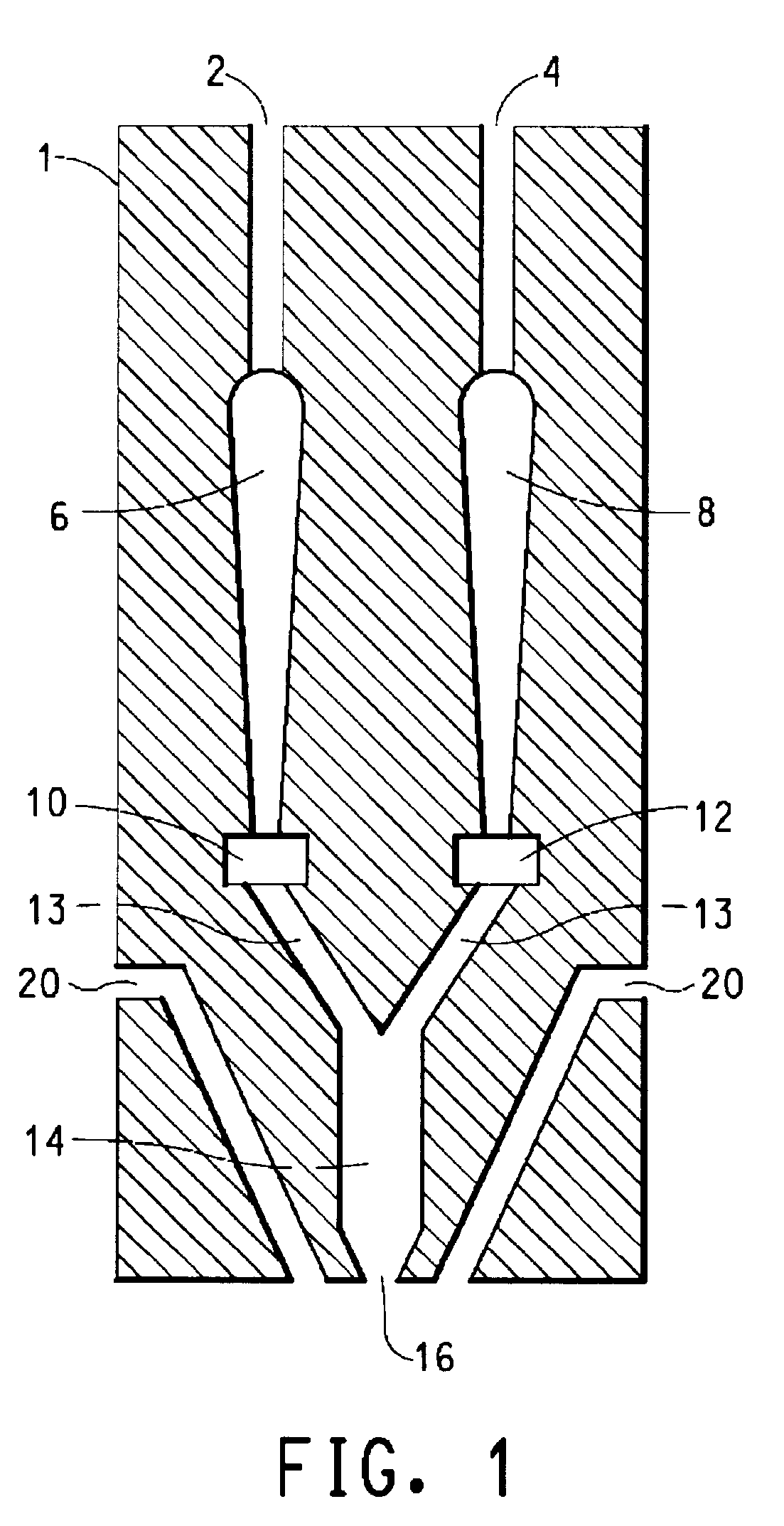
A meltblown bicomponent web was made from melt blown fibers with a polyethylene component and a poly(ethylene terephthalate) component. The polyethylene component was made from linear low density polyethylene with a melt index of 135 g / 10 minutes available from Equistar as GA594. The polyester component was made from poly(ethylene terephthalate) with an intrinsic viscosity of 0.53 available from E. I. duPont de Nemours and Company as Crystar.RTM. polyester (Merge 4449). The polyethylene polymer was heated to 260.degree. C. and the polyester polymer was heated to 305.degree. C. in separate extruders. The two polymers were separately extruded and metered to two independent coat hanger-type polymer distributors. The planar melt stream exiting each distributor were filtered independently and then combined in a bicomponent meltblowing die to provide a side-by-side filament cross section. The die was heated to 305.degree. C. The die had 645 capillary openings arranged in a 54.6 cm line. T...

example 2

A web was made according to the procedure in Example 1 except that the polyester component contained 0.05 percent blue pigment (11582-F25 Blue Phthalo available from Americhem, Inc.). The pigment was introduced with an additive feeder to the extruder throat in a 25 percent concentrate form where the base material was DuPont Crystar.RTM. (Merge 4449). The meltblown web had a basis weight of 17 g / m.sup.2. No significant difference in processibility was observed due to the presence of the pigment.

Filtering of the planar molten polymer flowstreams resulted in the virtual elimination of plugging of the spinneret exit orifices, thus enhancing uniformity of the nonwoven webs formed, and extending the up-time of the spinning system.


PUM

PropertyMeasurementUnit
pressureaaaaaaaaaa
temperatureaaaaaaaaaa
lengthaaaaaaaaaa

Abstract

The present invention is directed to a process for forming a plurality of multi-layered filaments from multiple thermoplastic synthetic polymers and an apparatus containing a melt spinning beam which comprises multiple polymer inlet passages each communicating with separate multiple coat hanger distribution manifolds, separate filters connected downstream of each coat hanger distribution manifold, a combining manifold connected downstream of said filters and spinneret orifices connected downstream of said combining manifold for spinning of said multi-layered filaments.

Description

BACKGROUND OF INVENTIONThis invention relates to a process and an apparatus for producing melt spun multi-layered cross section multi-component filaments. These filaments can be collected and processed into nonwoven webs for use in filters, apparel, wipes, and hygiene products.In a melt spinning process, thermoplastic synthetic polymers are melted and forced through orifices of a spinneret to form filaments. These filaments can be drawn or attenuated via air jets or mechanical means and collected on a moving porous surface to produce a random laydown of filaments or nonwoven web. The web can be bonded together to maintain its integrity. Also, in a melt blowing process, air jets can be added at the end of the spinneret to provide a very rapid drawing process providing very small diameter filaments.In order to produce uniform filaments from a row of spinneret orifices, the polymer of each filament should be subjected to as nearly as possible the same heat history and residence time in...

Claims


Application Information

Patent Timeline
Patent Type & Authority Patents(United States)
IPC IPC(8): D01D5/32D01D5/30D01D5/08D01D5/098
CPCD01D5/0985D01D5/32
Inventor RUDISILL, EDGAR N.BANSAL, VISHALDAVIS, MICHAEL C.
Owner 3M INNOVATIVE PROPERTIES CO
Why Eureka
Try Eureka