Stereoscopic endocsope system and TV imaging system for endoscope

a technology of endocsope system and endoscope, which is applied in the field of endocsope system and tv imaging system for endoscope, can solve the problems of difference in magnification between right and left images, large number of parts, and complex assembly

Inactive Publication Date: 2003-08-12
OLYMPUS OPTICAL CO LTD
View PDF26 Cites 94 Cited by
  • Summary
  • Abstract
  • Description
  • Claims
  • Application Information

AI Technical Summary

Problems solved by technology

By contrast, one of the drawbacks of the stereoscopic endoscope 10 lies in that since the right and left optical systems are constructed independently, the number of parts is large.
Consequently, assembling is complex.
Moreover, a difference in magnification between right and left images occurs deriving from an error of each part, and a shift of a focal point are large, and fine adjustment is required for normal stereoscopy.
Therefore, while right and left images are sharing the same optical path, a change of an image deriving from errors caused during manufacturing occurs in the right and left images in the same manner.
On the other hand, one of the drawbacks of the stereoscopic endoscope 20 is that three-dimensionality cannot be determined irrespective of specifications including an angle of view.
By contrast, a drawback of the stereoscopic endoscope 30 lies in that when lenses ending with the entrance pupil formation lenses are integrated into a scope unit and lenses succeeding the entrance pupil formation lenses are integrated into a TV camera unit, the orientations of images cannot be corrected by turning the units relative to each other.
Light beams are therefore obstructed by the turning.
However, even in case the stereoscopic endoscopes are used selectively according to the purpose of use, the drawbacks below occur.
Therefore, if a scope unit whose relay optical system has an aperture stop of a small diameter is mounted, light beams are obstructed.
This leads to a larger amount of wasted light.
This poses a serious problem costwise.
Moreover, even if any type of TV camera unit is used, it is impossible to replace the corresponding scope unit with any other type of scope unit and couple it with the TV camera unit.
This poses a problem costwise.
The TV camera unit is incompatible with the one for a rigid scope used for normal observation.
This leads to a large number of parts.

Method used


Image

  • Stereoscopic endocsope system and TV imaging system for endoscope
  • Stereoscopic endocsope system and TV imaging system for endoscope
  • Stereoscopic endocsope system and TV imaging system for endoscope

Examples


Embodiment Construction

Referring to the drawings, embodiments of the present invention will be described below.

Referring to FIGS. 4 to 6, the first embodiment of the present invention will be described.

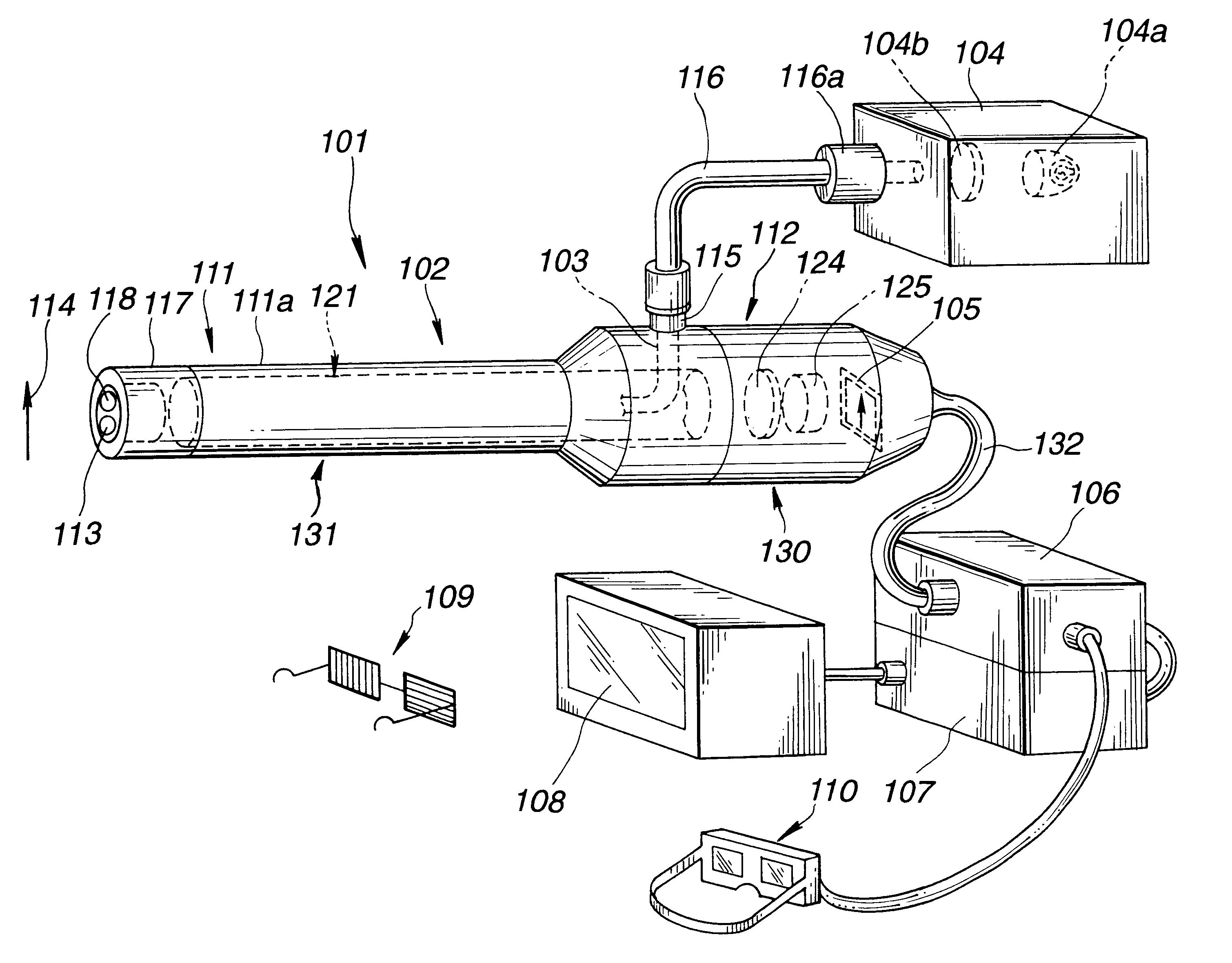
As shown in FIG. 4, a stereoscopic endoscope system 101 comprises: a stereoscopic endoscope 102 including an imaging optical system and illumination optical system used for stereoscopy; a light guide 103 serving as an illumination light conveying means lying through the stereoscopic endoscope 102; a light source apparatus 104 including, for example, a lamp 104a for generating illumination light of white light and thus supplying the illumination light, and a lens 104b for converging the white light; a camera control unit 106 (hereinafter a CCU 106) for processing electric signals sent from an imaging device 105 serving as an imaging means incorporated in the stereoscopic endoscope 102; a scan converter 107 for converting signals output from the CCU 106 into video signals; a color monitor 108 for displaying v...


PUM


Abstract

An armor (111a) of a scope unit (131) and a diaphragm (123) are arranged to be mutually freely turnable. The shape of an outer section (123c) of the diaphragm (123) and the shape of the inside of a scope joint (130a) of a TV camera unit (130) substantially agree with each other, and the outer section (123c) of the diaphragm (123) and the inside of the scope joint (130a) engage with each other. In a state in which the outer section (123c) of the diaphragm (123) and the inside of the scope joint (130a) are engaged with each other, a ring screw (133) is meshed with a thread (130b) so that the scope unit (131) and TV camera unit (130) will unitedly be joined with each other. At this time, since the outer section (123c) of the diaphragm (123) is engaged with the scope joint (130a), the diaphragm and TV camera unit can be turned relative to an objective optical system (119) and relay optical system (121) with the optical axis of the relay optical system (121) as an axis of turning. Moreover, a liquid-crystal shutter 124 in the TV camera unit (130) has two interceptive areas (124a, 124b) which can be switched temporally alternately. The interceptive areas (124a, 124b) intercept one of two light beams passing through either of aperture stops (123a, 123b).

Description

The present invention relates to a stereoscopic endoscope system and a TV imaging system for an endoscope which are used to observe an object three-dimensionally.BACKGROUND TECHNOLOGYIn recent years, endoscopes each having an elongated insertion unit thereof inserted in a body cavity for observation of an organ in the body cavity and making it possible to use if necessary a treatment appliance inserted in a treatment appliance channel to conduct various curative procedures have been adopted widely. Moreover, industrial endoscopes have been widely utilized for observation, inspection, or the like of flaws, corrosion, or the like inside a pipe in a boiler, gas turbine, engine, chemical plant, or the like or inside a body of an automobile engine.The endoscopes include a flexible endoscope whose insertion unit is flexible and inserted in a curved body cavity through a mouth or the like in order to observe or diagnose a lesion in the body cavity, and a rigid endoscope whose insertion uni...

Claims


Application Information

Patent Timeline
Patent Type & Authority Patents(United States)
IPC IPC(8): A61B1/00G02B23/24A61B1/002A61B1/04H04N15/00
CPCA61B1/00193G02B23/2415G02B23/2484A61B1/00188A61B1/042A61B1/055
Inventor NAKAMURA, SHINICHI
Owner OLYMPUS OPTICAL CO LTD
Why Eureka
Try Eureka