
Friction clutch

a clutch and friction technology, applied in the field of friction clutches, can solve the problems of complex multi-stage process, limited cooling air supply to the interior of the clutch, and clutch overheating,

Inactive Publication Date: 2003-08-26
ZF FRIEDRICHSHAFEN AG
View PDF11 Cites 8 Cited by
  • Summary
  • Abstract
  • Description
  • Claims
  • Application Information

AI Technical Summary

Benefits of technology

As a result of this measure, it becomes less expensive to fabricate the friction clutch, especially when castings are used, and fewer work steps are required to assemble it.
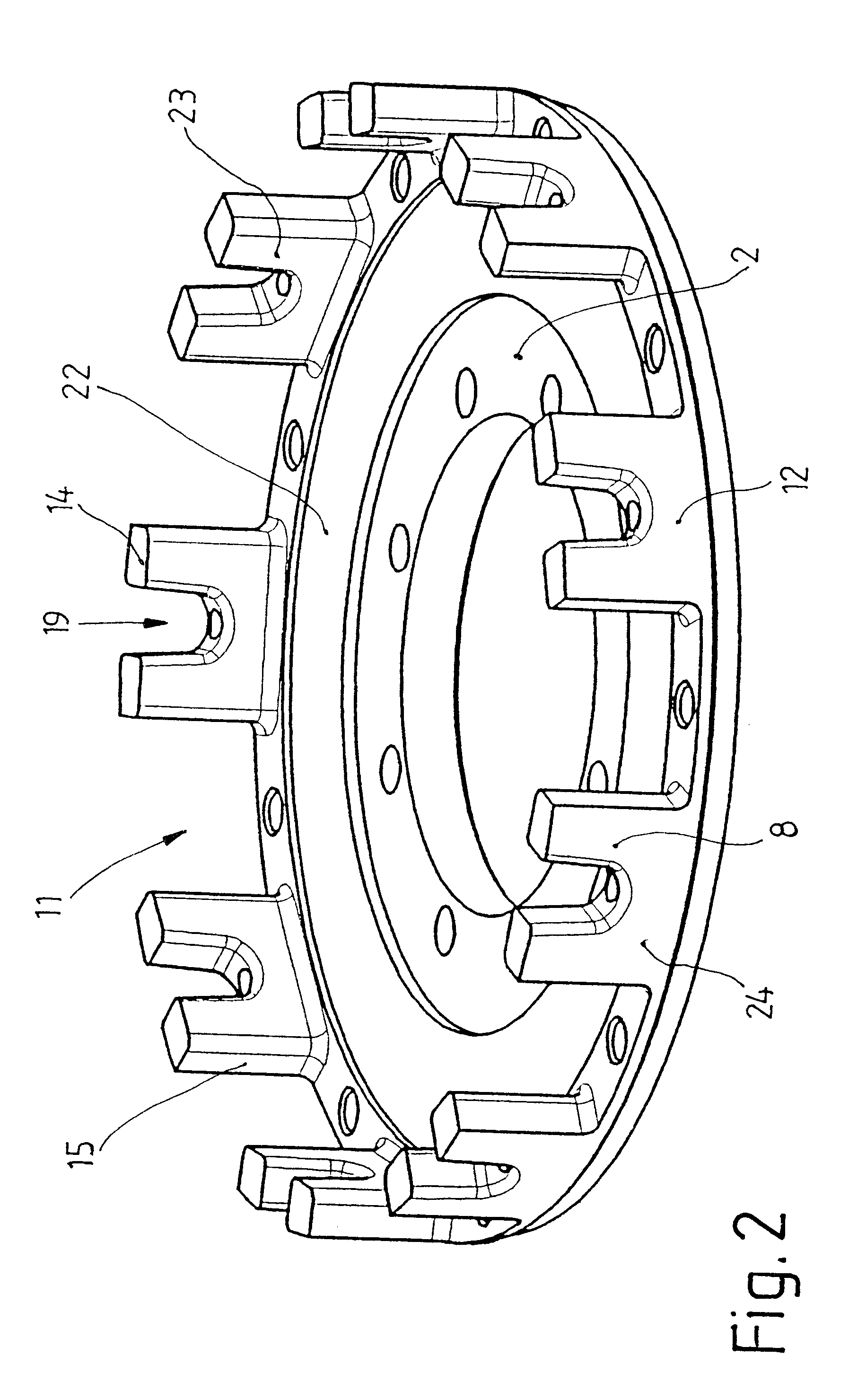
In a concrete embodiment of the invention, it is preferable for each wall to have an attachment section near the base of the input part to cooperate with a fastening means. In addition, an area where the fastening means is subjected to an elastic load is provided next to the attachment section in the axial direction. This makes it possible, first, to increase the stiffness of the input part with respect to the shrouding and, second, to minimize the effects of centrifugal force on the axial wall. This is because the attachment section reduces the bending stresses which occur in the base area of the axial wall as a result of centrifugal force; at the same time, if a certain part of the fastening means is free to be elastically deformed, the fastening means can be preloaded in a controlled manner. To keep down costs and to minimize the amount of work required to manufacture the input part, it is also proposed that the area where the fastening means is deformed be provided in the wall. While elastic load is being exerted on the fastening means, furthermore, the housing will also be elastically deformed in the attachment area. By designing the area of the housing near the fastening means and the area of the housing where it makes contact with the input part in such a way that the housing is elastically deformed at least in the axial direction, it is possible to increase even more the reliability of the assembly process and to reduce the error rate with respect to defective connections. For this purpose, either the housing can have a bulge pointing away from the fastening direction in the contact area with the fastening means, or alternatively the input part can have a depression in this area. The housing is preferably supported in this case against the end surface of the part of the wall extending in the axial direction; there can be one of these end surfaces at each circumferential end of each attachment area.
To reduce the stresses resulting from centrifugal forces, the housing can have an outer area which works together with centering sections of the walls. This is also an especially simple way of centering the housing and the input part with respect to each other and their common axis of rotation.

Problems solved by technology

In a friction clutch of this type, there is the problem that the supply of cooling air to the interior of the clutch is limited.
This means that the clutch can overheat at least when it is slipping for an extended period of time.
This known friction clutch also suffers from the problem that the housing is manufactured by means of complicated, multi-stage processes.

Method used


Image

  • Friction clutch
  • Friction clutch
  • Friction clutch

Examples


Embodiment Construction

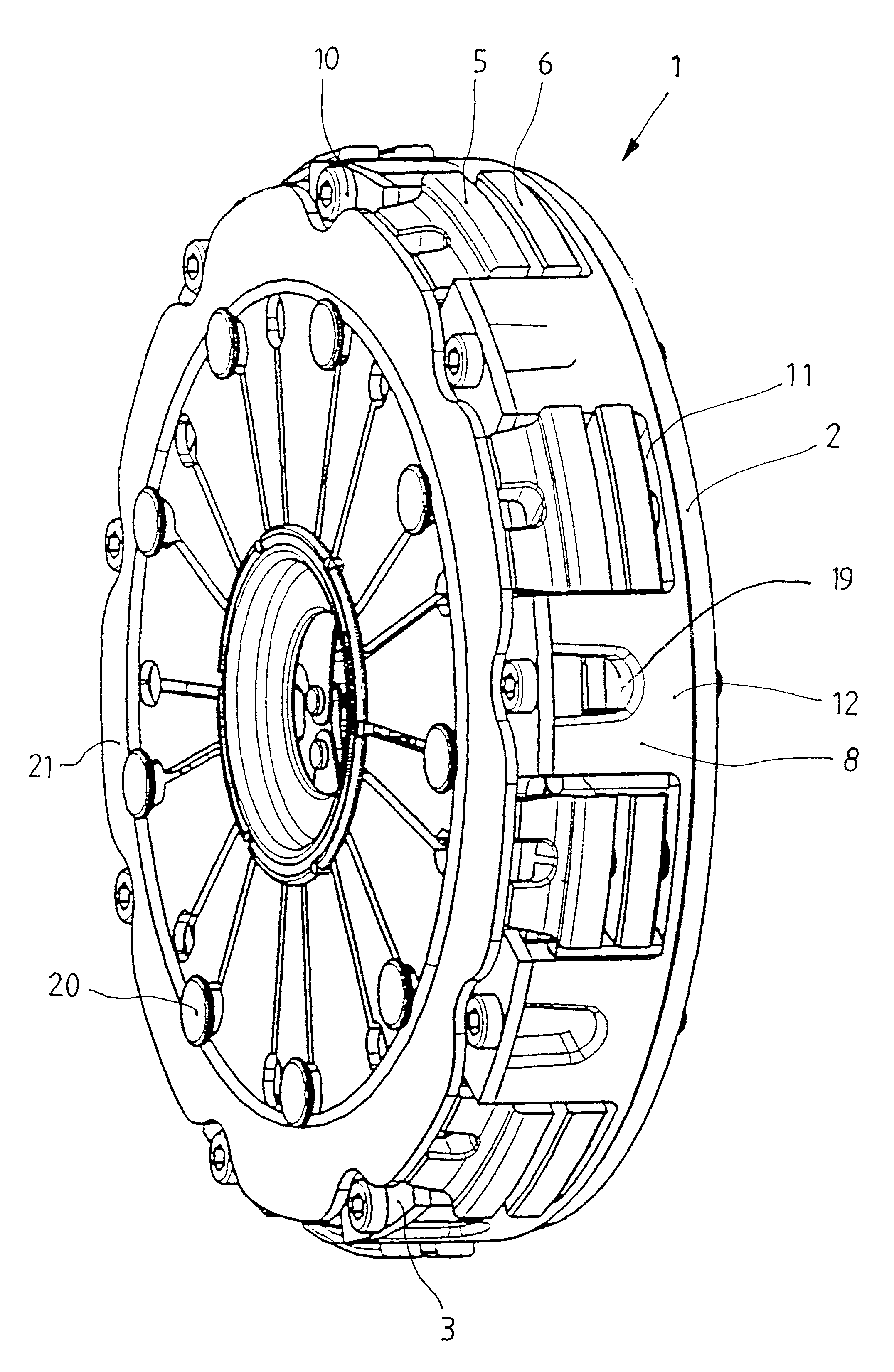
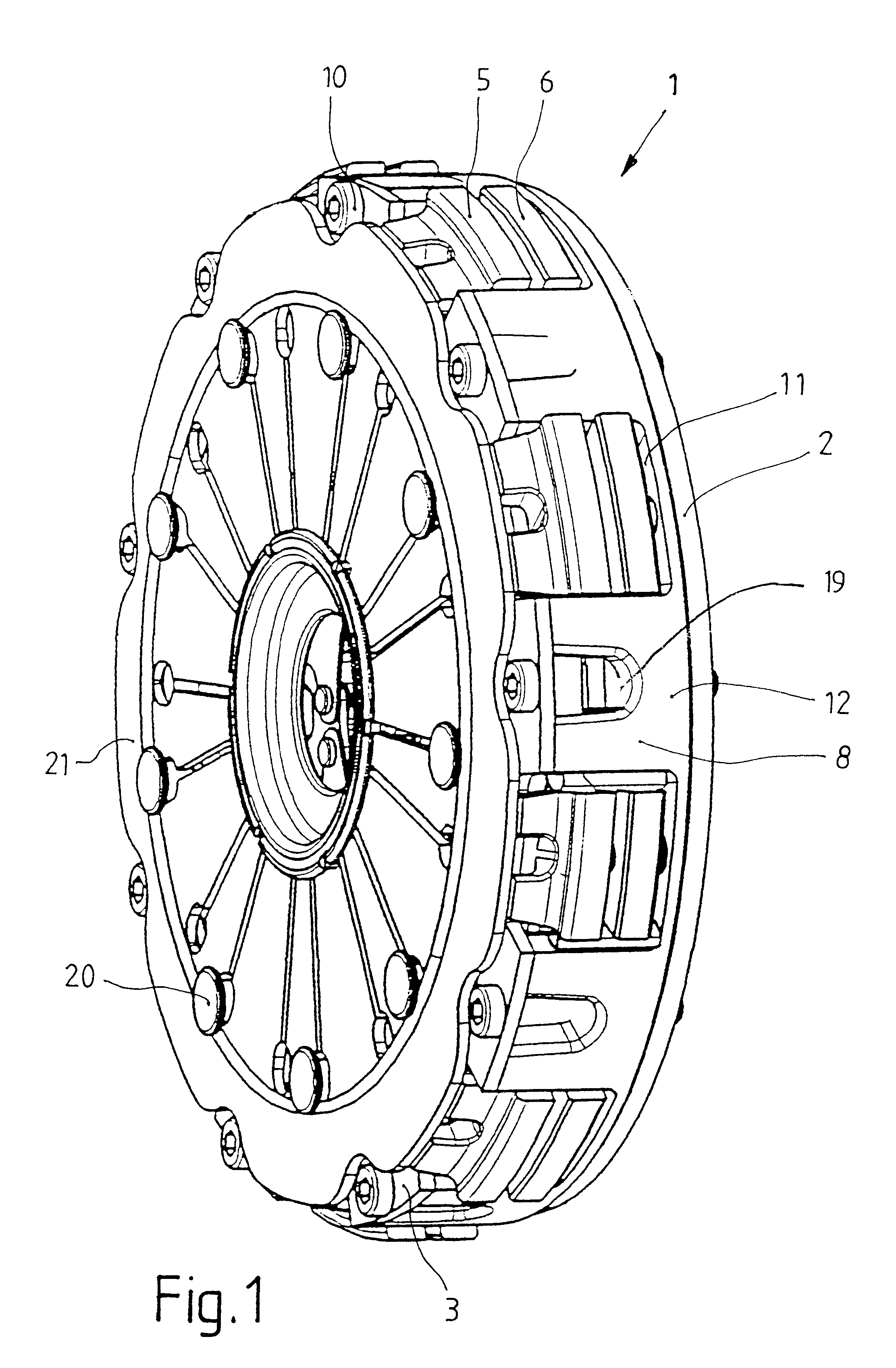
The friction clutch 1 shown in perspective in FIG. 1 consists primarily of an input part 2, which is flanged to the crankshaft of an internal combustion engine; a housing 3, which is attached to the end surface of the input part; and a stored energy element in the form of diaphragm spring 21, which is supported against the axial side of the housing by spacer bolts 20 so that the spring is free to move back and forth. This diaphragm spring 21 acts on knife edges formed on the pressure plate 5 and thus presses the plate in the engaged state against the clutch disk. With respect to its design and function, the friction clutch 1 shown here corresponds for the most part to the friction clutch described in U.S. Pat. No. 6,409,002, the content of which is incorporated herein by reference.

The housing 3 shown in FIG. 3 is connected to the input part 2 by fastening means, which are designed here as screws 10. These screws pass through attachment holes in the radially outer tabs of the housing...


PUM


Abstract

Friction clutch for use in the drive train of a motor vehicle with an input part, a clutch housing, at least one clutch disk in working connection with a takeoff element, and a pressure plate working together with the input part, the force of a stored-energy element acting on the pressure plate to transmit torque to the clutch disk. The radially outer area of the input part has axially oriented walls extending along at least part of the circumference to cooperate with the pressure plate.

Description

1. Field of the InventionThe present invention pertains to a friction clutch for use in the drive train of a motor vehicle with an input part, a clutch housing, at least one clutch disk in working connection with a takeoff element, and a pressure plate working together with the input part, the force of a stored-energy device acting on the pressure plate to transmit torque to the clutch disk.2. Description of the Related ArtU.S. Pat. No. 5,779,018 discloses a multi-disk friction clutch in which the several clutch disks are designed in the form of a set of plates connected to a common hub part. In the clutch housing, a pressure plate is provided, which can be acted upon by a stored-energy device, and in addition several intermediate disks are connected nonrotatably to the clutch housing, these intermediate disks engaging between the plates. By means of the stored-energy device, the intermediate disks and the plates can be pressed against each other to generate mutual frictional contac...

Claims


Application Information

Patent Timeline
Patent Type & Authority Patents(United States)
IPC IPC(8): F16D13/58F16D13/70F16D13/72
CPCF16D13/70F16D13/72
Inventor VOGT, SEBASTIAN
Owner ZF FRIEDRICHSHAFEN AG
Learn More