Pulse tube liner

a technology of pulse tube and liner, which is applied in the direction of gas cycle refrigeration machines, refrigeration machines, lighting and heating apparatus, etc., can solve the problems of low heat capacity and poor heat transfer between the liner and the wall of the pulse tube, and achieves relatively good heat transfer between the fluid and the liner, and low heat capacity. , the effect of low heat capacity

Inactive Publication Date: 2003-09-16
MITCHELL MATTHEW P
View PDF3 Cites 23 Cited by
  • Summary
  • Abstract
  • Description
  • Claims
  • Application Information

AI Technical Summary

Benefits of technology

A thin liner fabricated from a strong material with relatively low heat capacity, preferably of metal, is installed in the pulse tube in close proximity to the pulse tube wall. Because the liner is in intimate contact with the fluid in the pulse tube, and because the fluid in the pulse tube is almost always in motion, heat transfer between the fluid and the liner is relatively good. Because the liner is in only intermittent contact with the wall of the pulse tube, and because the thin layer of fluid trapped between the liner and the wall of the pulse tube is stagnant, heat transfer between the liner and the wall of the pulse tube is relatively poor. Because the liner itself is thin, its heat

Problems solved by technology

Because the liner is in only intermittent contact with the wall of the pulse tube, and because the thin layer of fluid trapped between the liner and the wall of the

Method used


Image

  • Pulse tube liner
  • Pulse tube liner
  • Pulse tube liner

Examples


Embodiment Construction

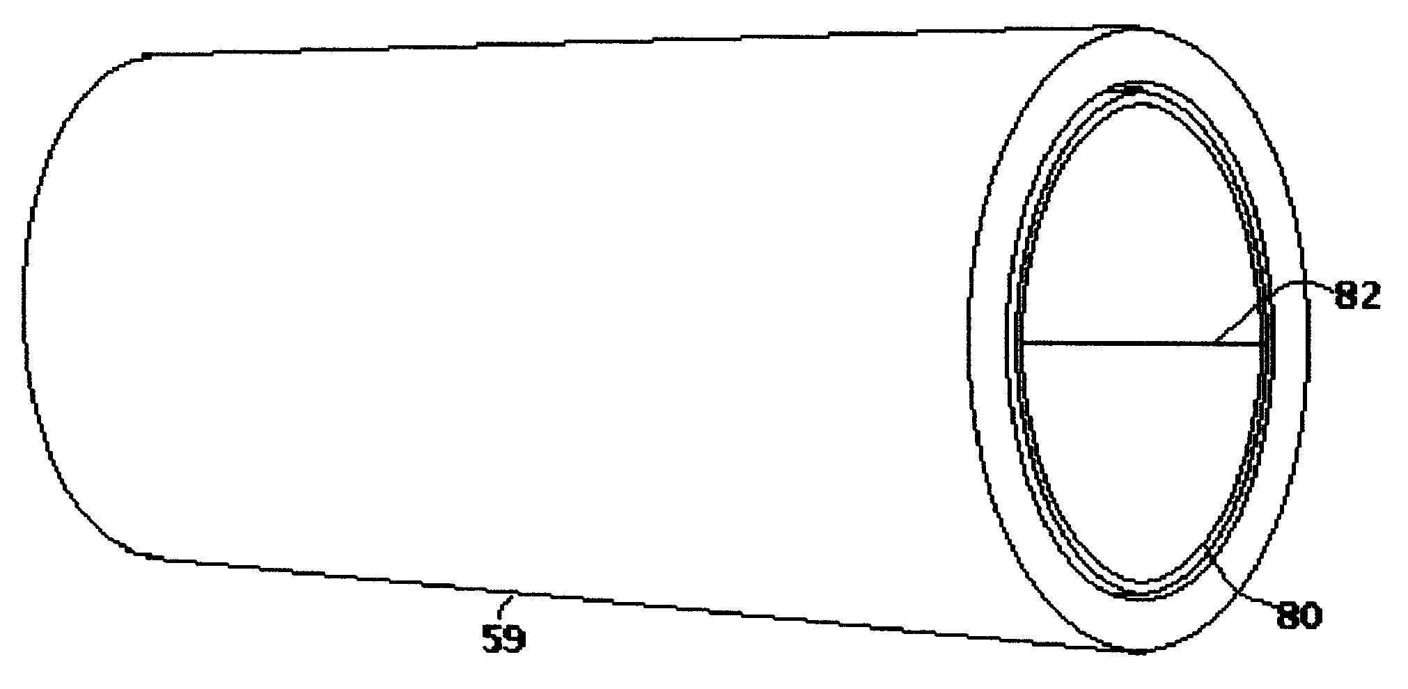
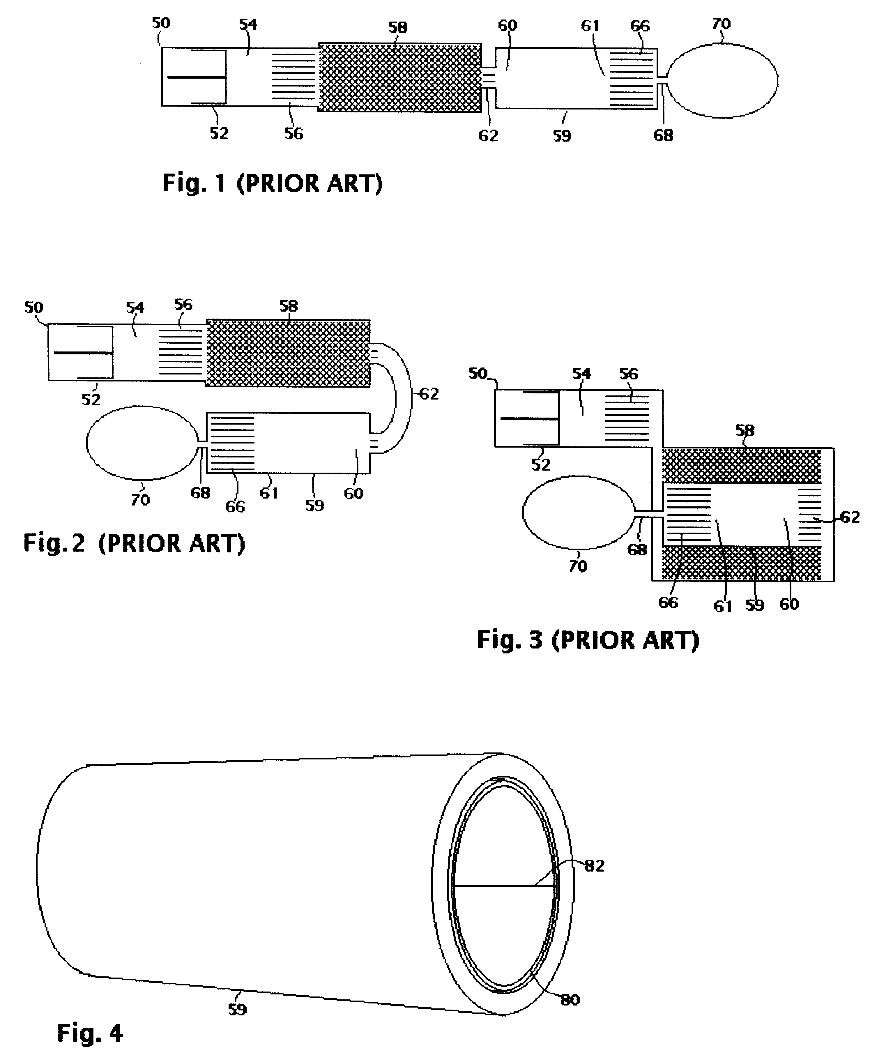
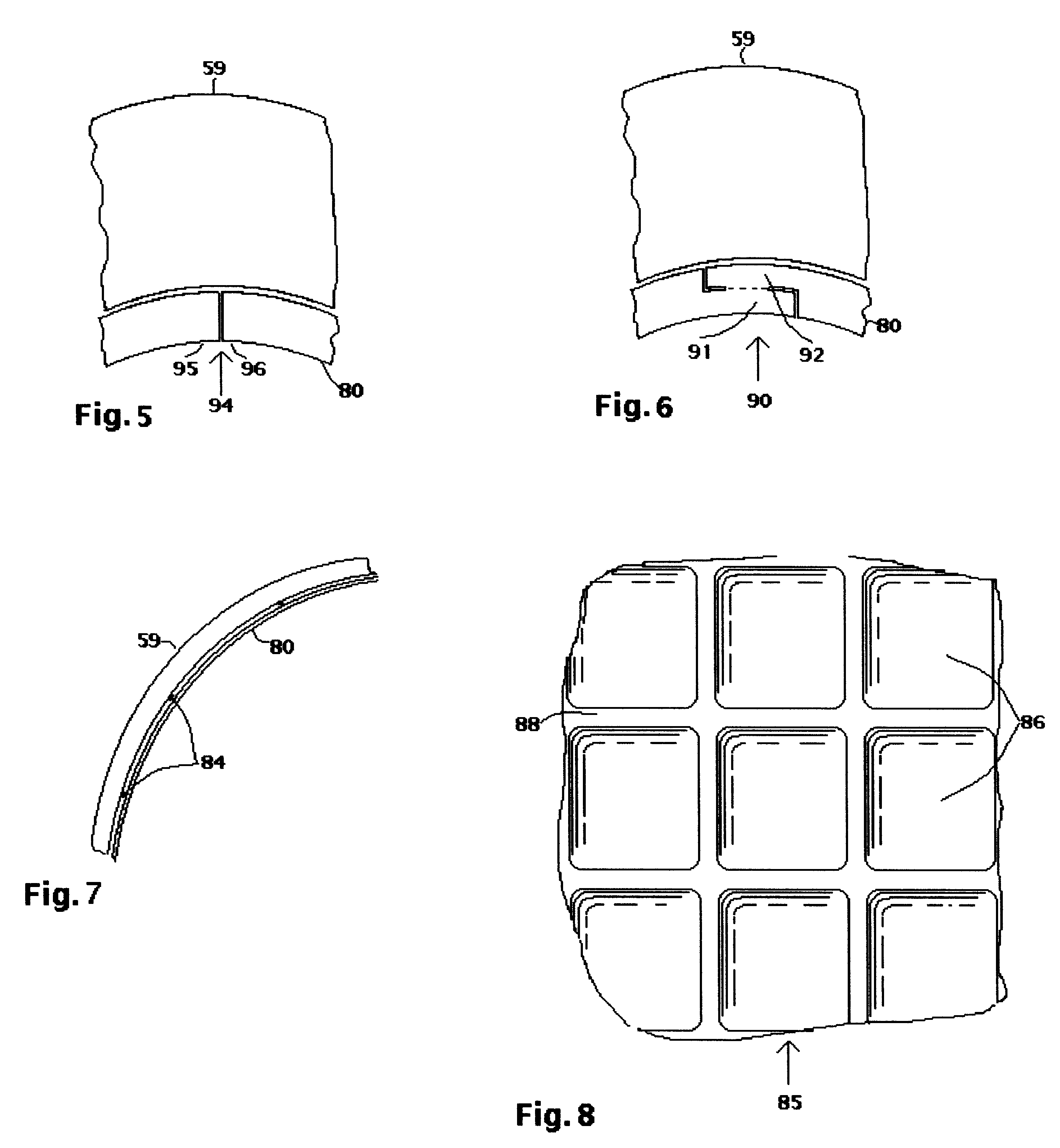
In a preferred embodiment of this invention, shown in FIG. 4, a layer of liner 80 is installed in pulse tube 59, which may be a pulse tube of a linear pulse tube refrigerator as shown in FIG. 1, a U-tube pulse tube refrigerator as shown in FIG. 2 or a coaxial pulse tube refrigerator as shown in FIG. 3. Pulse tube 59 may be of any material. Pulse tube 59 will typically have a wall thickness of 0.15 mm or greater. Liner 80 will typically have a maximum thickness of about 0.055 mm or less. Joint 82 in FIG. 4 may be a butt joint as shown in FIG. 5 or a welded joint as shown in FIG. 6. Alternatively, a tube of similar thickness formed by any other process, would be equivalent. For lowest cost, liner 80 may be smooth stainless steel or titanium foil. Alternatively, where higher cost is justified, liner 80 may be recessed foil, preferably fabricated from 0.0254 mm 316 L stainless steel, full hard, or 0.0305 mm titanium foil etched in the pattern shown in FIG. 8, with foil in indented reces...


PUM


Abstract

The pulse tube 59 of a pulse tube refrigerator is equipped with a thin liner 80 of low thermal mass and in poor thermal contact with pulse tube 59. One surface of liner 80 may be furnished with indented recesses 86, making the recessed portions of the liner thinner than the remainder of the material of liner.

Description

Application Ser. No. 09 / 084,042 of Matthew P. Mitchell for Concentric Foil Structure for Regenerators.1. Background--Field of InventionThe invention relates to liners for the walls of the pulse tube portions of pulse tube refrigerators.2. Background--Description of Prior ArtPulse tube refrigerators are regenerative gas cycle refrigerators typically used as cryocoolers, providing cooling at temperatures below about 120 Kelvin. Pulse tube refrigerators are characterized by a tube, called the "pulse tube" in which a compressible fluid, typically helium, is cyclically shuttled back and forth while the pressure of the fluid, and thus its temperature, is cyclically changing. One end of the pulse tube becomes warm as warm, compressed fluid repeatedly moves toward the warm heat exchanger, where heat is rejected. The other end of the pulse tube becomes cold as fluid at lower pressure repeatedly moves toward the cold heat exchanger, where heat is lifted from the cooling load. In operation, fl...

Claims


Application Information

Patent Timeline
IPC IPC(8): F25B9/14
CPCF25B9/145F25B2309/1407F25B2309/1413F25B2309/1414F25B2309/1424F25B2309/1406
Inventor MITCHELL, MATTHEW P.
Owner MITCHELL MATTHEW P
Why Eureka
Try Eureka