Image forming device capable of detecting existence of ink and ink cartridge with high accuracy

a technology of ink and ink cartridges, applied in printing and other directions, can solve the problems of sensor inability to detect, affecting the detection accuracy of ink cartridges, and difficult to slant the optical sensor at the prescribed angl

Inactive Publication Date: 2003-09-16
BROTHER KOGYO KK
View PDF6 Cites 37 Cited by
  • Summary
  • Abstract
  • Description
  • Claims
  • Application Information

AI Technical Summary

Benefits of technology

It is another object of the present invention to provide an image-forming device having a simple construction and capable of reliably calibrating the intensity of light irradiated from the optical ink sensor to detect with accuracy the existence of ink and ink cartridge.
It is another object of the present invention to provide an image-forming device capable of detecting the existence of ink without slowing the processing speed of the image-forming device.
It is another object of the present invention to provide an image-forming device employing prisms to form alternate peaks and valleys on the ink cartridge and capable of accurately detecting the existence of ink cartridges and of ink inside the ink cartridges while the ink cartridges are moving.
There is also provided an image forming device including at least one cartridge, a sensor, a carriage, a control unit, and a detecting unit. The at least one cartridge contains an ink and has an irradiated portion. The sensor that detects an amount of reflected light reflected from the irradiated portion of the cartridge. The sensor includes a light emitting unit that irradiates a light onto the cartridge at the irradiated portion and a light receiving unit that receives the reflected light The carriage mounts the cartridge thereon and reciprocally moves along with the cartridge. The control unit controls an intensity of the light irradiated from the light emitting unit. The detecting unit moves the carriage to a predetermined position where the light irradiated from the light emitting unit is irradiated on the cartridge at the irradiated portion and detects an amount of the ink contained in the cartridge based on the amount of reflected light detected by the sensor. The detecting unit detects existence of the ink in the cartridge when a level of the ink containing in the cartridge is above the irradiated portion. The control unit controls the intensity of the light such that the detecting unit detects the existence of the ink when the level of the ink is above the irradiated portion of the cartridge based on the amount of reflected light reflected from the irradiated portion of the cartridge that contains a brightest-color ink. With this configuration, accurate detection of the existence of the ink cartridge and the ink in the ink cartridge is achieved.
By using the brightest ink cartridge to adjust the amount of light emitted from the light-emitting element, accurate detection can be achieved even when the sensitivity of the ink sensor is irregular. Further, by performing such adjustments using the ink cartridge with the brightest ink, suitable detection can be reliably performed on ink cartridges containing other inks that are less bright. Therefore, a single adjustment value can be applied to all ink cartridges when multiple colors of ink are used, thereby simplifying the process and reducing the processing time.
With this configuration, because the detecting unit detects the amount of the ink contained in the cartridge during the paper-feed interval, there is no need to put printing operations on standby, thereby improving processing speed of the image forming device.

Problems solved by technology

Such a light consists a noise signal, thereby degrading the detecting precision.
However, it is difficult to slant the optical sensor at the prescribed angle in relation to the irradiation surface of the ink cartridge.
As a result, the optical sensor cannot detect the light or a portion of the light that is reflected from the ink cartridge at the intended detecting position and cannot, therefore, accurately detect the existence of ink or of a mounted ink cartridge.
Further, due to irregularities in its sensitivity, the optical sensor may not achieve precise detection when the intensity of irradiated light from the light-emitting element is uniform.
This leads to an increase in complexity and duration of the calibration process.
However, it is difficult to estimate appropriate calibration values for other ink cartridges using this method, because the amount of light reflected from the ink cartridge varies according to the color of ink contained therein.
Hence, while it is possible to detect with high accuracy the amount of ink remaining in the ink cartridge for which reflected light has been actually measured, it is not possible to measure with accuracy the amount of ink remaining in ink cartridges using the estimated value.
Because recording operation cannot be performed during this time interval, detecting the existence of ink during the recording operation reduces the processing speed of the recording device.
However, since this conventional device is configured with only a single optical sensor to detect the existence of ink in a plurality of ink cartridges, the carriage supporting the ink cartridges must be continually moved while the optical sensor is irradiating a light onto each ink cartridge to detect the existence of ink therein.
Since the amount of reflected light varies depending on whether it is reflected from a valley or a peak in the prisms or therebetween, the waveform read by the optical sensor has a zigzag shape Accordingly, it is not always possible to detect the existence of ink with accuracy at some reading points.

Method used


Image

  • Image forming device capable of detecting existence of ink and ink cartridge with high accuracy
  • Image forming device capable of detecting existence of ink and ink cartridge with high accuracy
  • Image forming device capable of detecting existence of ink and ink cartridge with high accuracy

Examples


first embodiment

As described above, according to the present invention, because the level of light emitted from the infrared light-emitting element 19a has been adjusted using the ink cartridge containing yellow ink, the ink sensor 19 can detect remaining ink with great accuracy, even when the ink sensor 19 has irregularities in sensitivity.

Since the amount of light reflected by the yellow ink cartridge is the largest, the present invention can still reliably detect remaining ink in the other ink cartridges when the amount of emitted light is adjusted to achieve proper ink detection in the yellow ink cartridge. Therefore, when the printer uses multiple colors of ink, it is possible to apply a single adjustment value to all ink cartridges, thereby simplifying the process and reducing the processing time.

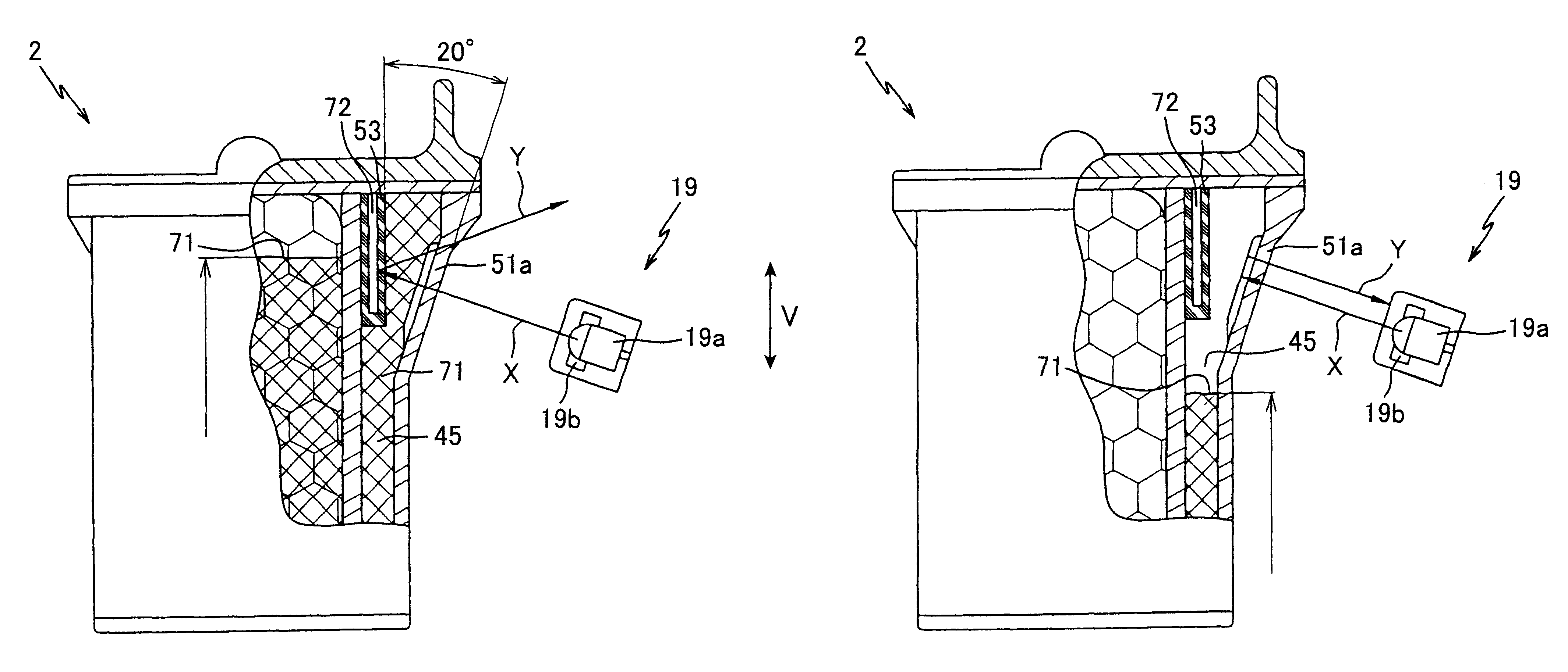
Moreover, since the level of light emitted from the infrared light-emitting element 19a is adjusted using the yellow ink cartridge 2d containing ink only in the sub ink reservoir 45, a precise adjust...

second embodiment

Next, the present invention will be described with reference to FIGS. 22(a) and 22(b). While the ink cartridge 2 of the first embodiment is configured with the reflecting member 53 to change the optical path of the infrared light, an ink cartridge 130 of the second embodiment includes an infrared light-absorbing member 131 for absorbing infrared light. Parts and components similar to those in the first embodiment are designated by the same reference numerals to avoid duplicating description.

FIGS. 22(a) and 22(b) are side views showing the ink cartridge 130 and the ink sensor 19 with a partial cross-sectional view of the ink cartridge 130. The mounting members and the like for the head unit 4 and ink sensor 19 are omitted from these drawings for illustration purposes.

Similar to the ink cartridge 2 of the first embodiment, the ink cartridge 130 of the present embodiment includes the prisms 52 formed on an inner surface of a sloped portion 51a on which infrared light is irradiated. The...


PUM


Abstract

In a calibration data input process, a carriage 5 is moved toward an ink sensor 19 to a prescribed position while the ink sensor 19 detecting levels of reflected light. Then the amount of reflected light is read for over a range wider than the width of the carriage 5 including a theoretical detecting position P2. An actual detecting position P1 is found based on the level of reflected light. The difference between the theoretical detecting position P2 and the actual detecting position P1 is calculated and is stored as the calibration value alpha in a first calibration data memory M1. Accordingly, the actual detecting position P1 is set as P2±alpha. The calibration value alpha is used in a calibration process to calibrate the detecting position, so that the level of reflected light can be detected with accuracy.

Description

1. Field of the InventionThe present invention relates to an image-forming device, such as an inkjet printer, having an optical sensor for detecting ink cartridges mounted in the device, as well as the existence of ink in the ink cartridges.2. Description of the Related ArtConventional inkjet printers used as image-forming devices, such as facsimile devices, photocopying devices, and the like, are provided with an optical sensor for optically detecting whether an ink cartridge is mounted in the device and whether the cartridge contains ink. This optical sensor includes a light-emitting element for radiating a light toward an ink cartridge, which is formed of an optically transparent material, and a light-receiving element for sensing the amount of light reflected by or permeated through the ink cartridge. Since the amount of light reaching the light-receiving element changes according to the existence of ink and the existence of an ink cartridge, the optical sensor can sense the exi...

Claims


Application Information

Patent Timeline
Patent Type & Authority Patents(United States)
IPC IPC(8): B41J2/175
CPCB41J2/17566B41J2002/17573
Inventor YOSHIYAMA, MASATOSHIMURAKAMI, ATSUSHIOUCHI, TETSUYAHAYAMIZU, KAZUHIRO
Owner BROTHER KOGYO KK
Why Eureka
Try Eureka