Filter apparatus for HVAC system

a filter and hvac system technology, applied in lighting and heating apparatus, heating types, separation processes, etc., can solve the problems of difficult access to filters, ineffectiveness, and low cost of filter elements, and achieve convenient maintenance and/or replacement, convenient and easy disposal, and large cross-sectional area

Inactive Publication Date: 2003-09-23
CLAYTON ROBERT L +1
View PDF19 Cites 39 Cited by
  • Summary
  • Abstract
  • Description
  • Claims
  • Application Information

AI Technical Summary

Benefits of technology

It is an object of the present invention to provide a filter apparatus for deployment over a duct end in a forced air HVAC system such that the apparatus may be conveniently and easily installed over either a supply duct or a return duct.
It is another object of the present invention to provide a filter apparatus for a forced air HVAC system such that the air passage through the apparatus is larger than the cross sectional area of the duct over which it is installed, thereby substantially reducing the static pressure drop across the filter apparatus and improving the filtration of airborne particulates.
It is still another object of the present invention to provide a filter apparatus such that a plurality of filter elements may be accommodated, and such that such filter elements may be conveniently and easily removed for maintenance without removing the filter apparatus from its position over the duct end in an HVAC system.
It is yet another object of the present invention to provide a filter apparatus for deployment over a duct end in a forced air HVAC system such that aesthetically pleasing designs may be incorporated therein.
Briefly, the present invention provides a filter apparatus comprising a frame that is conveniently and easily disposed over a duct end in a forced air HVAC system, a filter element that is removably disposed within said frame, means to achieve easy access to said filter element for easy maintenance and / or replacement, and incidental related items to support the principal components identified herein. Unlike many forms of prior art filter apparatus, the filter apparatus of the present invention is not limited in size to the duct end over which it is installed, or a register to which it might be secured. In a preferred embodiment of the present invention, the filter elements are significantly larger in cross-sectional area than either the duct or the openings in an intervening register. Accordingly, the filter apparatus described herein thus provides significantly lower pressure drop across the filter element than prior art filter apparatus while improving filtration efficiency.
The filter apparatus of the present invention is provided with an opening in the side of the filter frame, over which a movable cover is fitted, so that the filter element may be easily removed for maintenance or replacement. Removal of the filter element is so simple that it may be performed by someone with little or no knowledge of the HVAC arts.

Problems solved by technology

However, the effectiveness of any filter apparatus depends on its design, and whether it is properly maintained.
However, if the heating / cooling apparatus is situated in a crawl space or attic, access to a filter is very difficult.
Such filter elements are inexpensive, but also ineffective.
Where access to the filter is difficult, maintenance may be nonexistent.
Typically, in a hot, dry climate, the air is very dusty and likely to contain dead vegetative matter.
In addition, bacteria and mold may grow in the HVAC apparatus, creating another class of undesirable contaminants in the moving air stream.
As evaporative coolers are frequently situated on the roof of a structure, rendering access to a filter located near the cooling unit impossible, filters are generally omitted from such HVAC apparatus.
In summary, filters in closed-loop HVAC systems are ineffective and filters in open-loop HVAC systems are nonexistent.
Yet another factor was the discovery that those skilled in the HVAC arts had not heretofore adequately addressed that need.
While the latter two patents disclose filters installed near the duct end, those filters are actually installed within the duct, which creates considerable inconvenience in installing the filter apparatus and considerable difficulty in maintaining the filter elements.
In short, none of these patents addresses the need for easy access to filter elements, to conveniently maintain those filter elements.
However, any filter element is essentially an obstruction in the HVAC system, and maintaining a high air velocity through a filter element will necessarily create a significant pressure drop in the stream of moving air.
The pressure drop that is an inescapable consequence of Hodge's teaching places a significant load on the blower in the HVAC system, and necessitates careful sealing of all the ducts in the system to control air leakage therefrom.
Furthermore, this excessive pressure drop is contrary to manufacturers' recommendations against high-density filters, which restrict air flow and possibly damage the HVAC equipment.
This problem is particularly acute in heat pump HVAC systems.
This necessarily limits the materials chosen for components of his filter apparatus to those that are not damaged by washing.
The limitation is more severe if the filter apparatus is washed in a dishwasher, as Hodge suggests.
Further, washing the entire filter apparatus may cause water to become entrapped in the channel that is an essential element of his teaching; such trapped water could leak onto the wall, or be blown into living space in the structure, if the filter apparatus in reinstalled before it is fully dry.
The problem of pressure drop across the filter element is the same as in the filter apparatus described in the '145 patent, and perhaps worse.
The teaching of the Hodge '719 patent with respect to removing the filter elements and retaining grids for maintenance, and subsequently reinstalling them, may be inoperative.
However, his apparatus is rather bulky and it requires a significant amount of disassembly to gain access to the filter.
Further, his location of the filter apparatus, namely, over a return air duct end, renders it inoperative with respect to evaporative cooling systems.
This is a serious limitation with respect to HVAC systems used in hot, dry climates.

Method used


Image

  • Filter apparatus for HVAC system
  • Filter apparatus for HVAC system
  • Filter apparatus for HVAC system

Examples


Embodiment Construction

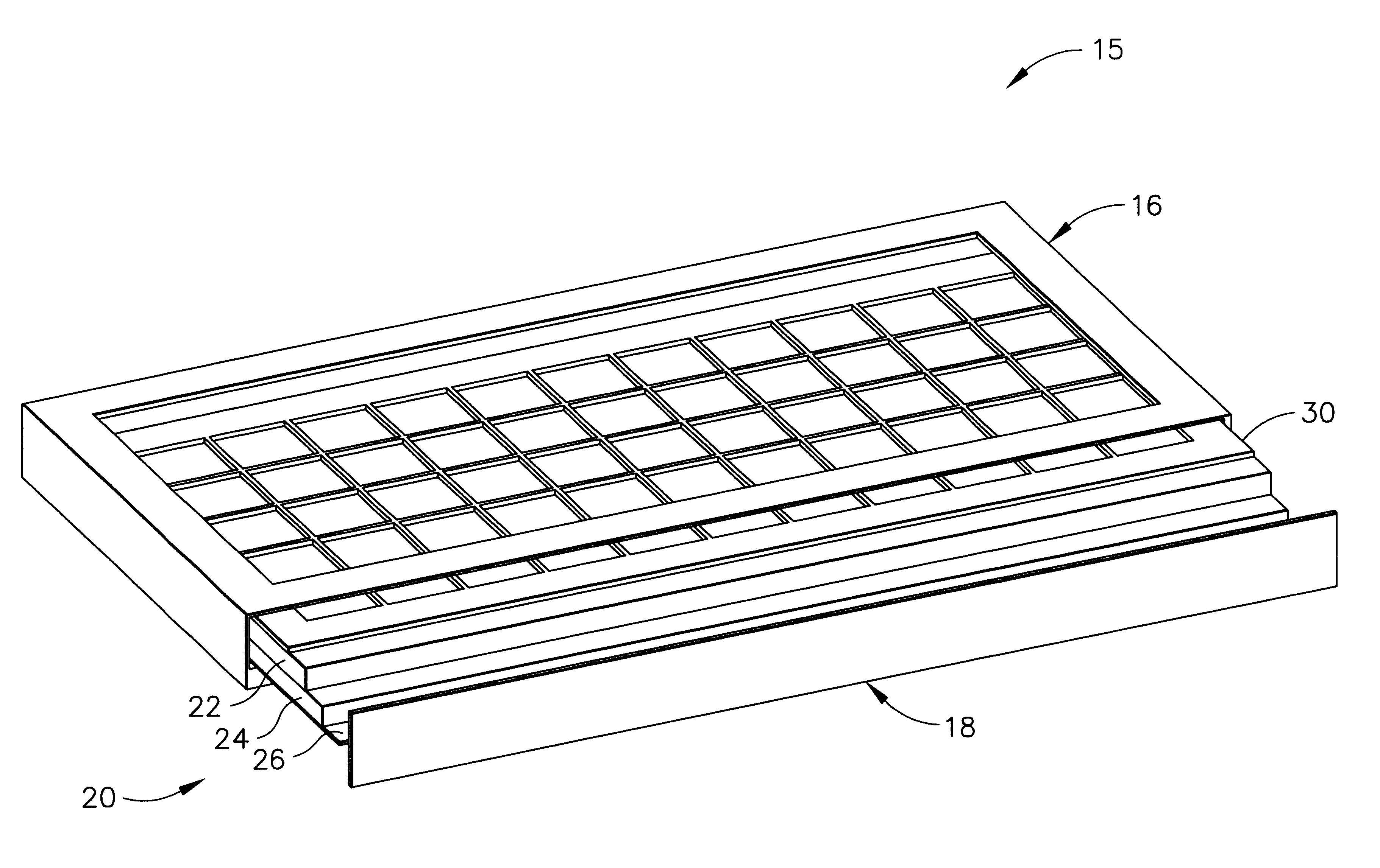
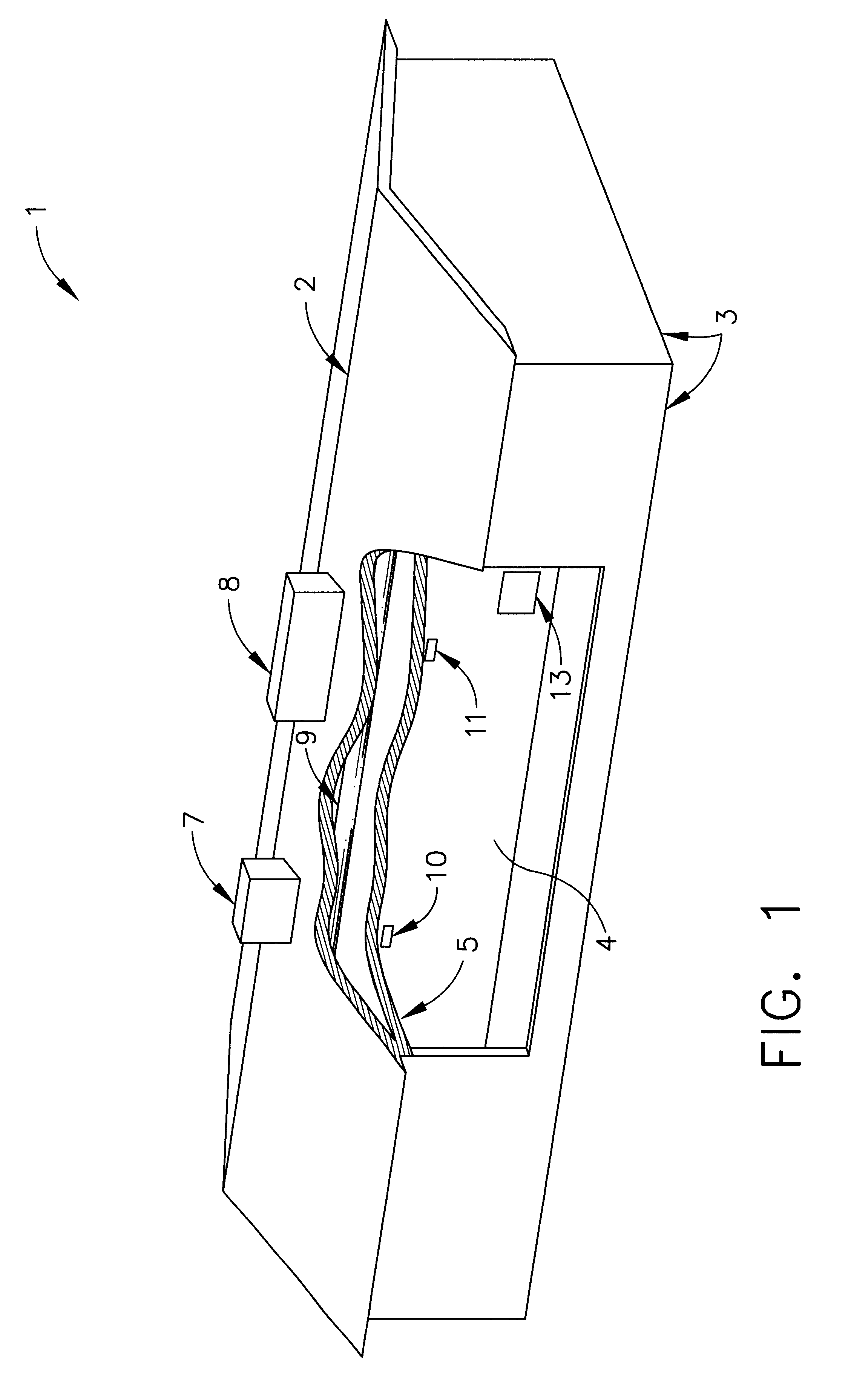
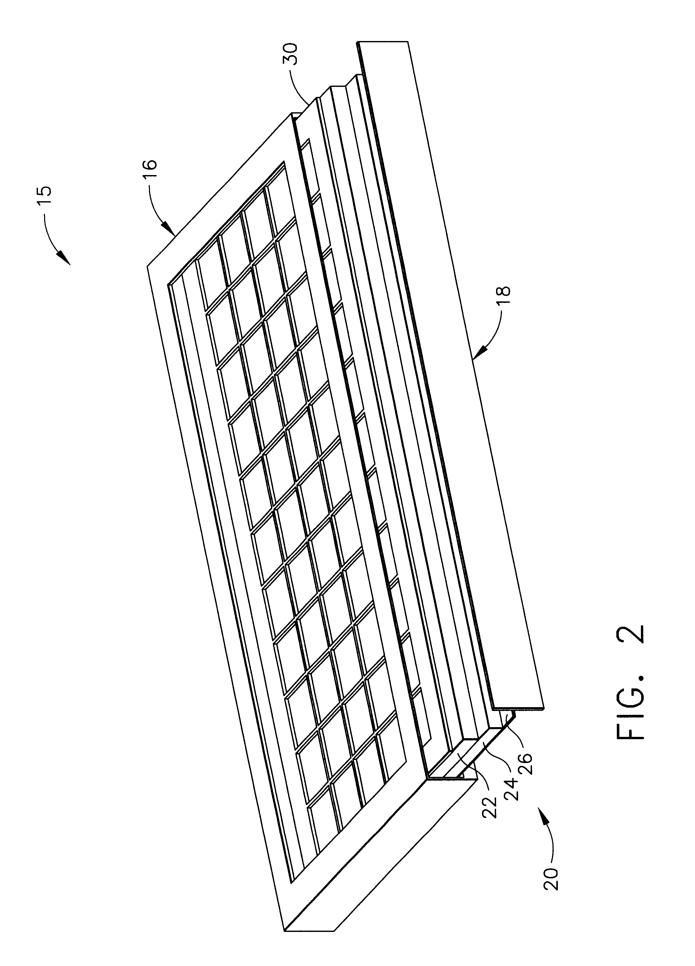
The filter apparatus of the present invention is advantageously described with reference to the Figures described hereinabove. The present invention is conveniently described in the context of one application therefor, namely, as part of an HVAC system employed in a residential structure in a hot, dry climate. Such a structure is shown schematically at 1 in FIG. 1. The principal elements of the structure are its roof 2, exterior walls 3, interior walls 4 and ceilings 5. FIG. 1 is not intended as a complete drawing of a house and the HVAC system employed therein, but rather as an illustration of principal features thereof. The principal elements of the HVAC system are an evaporative cooler 7, a combination heater-cooler 8, a main distribution duct 9, supply registers 10 and 11, and a return register 13. Note that the evaporative cooler 7 and the heater-cooler 8 are commonly situated on the roof of the structure. Each is connected to the main distribution duct 9 via a connecting duct,...


PUM

PropertyMeasurementUnit
temperaturesaaaaaaaaaa

Abstract

A filter apparatus for deployment over a duct end in a forced air heating / ventilating / air conditioning system is described. The apparatus has been specifically designed for easy installation, and also for convenient cleaning and maintenance by occupants of the structure where the apparatus is employed. The apparatus preferably overhangs the duct end, thereby allowing improved filtration efficiency and reduced air pressure drop across the filter apparatus.

Description

1. Field of the InventionThis invention relates generally to forced air heating, ventilating and air conditioning systems and more particularly to a filter unit used at the end of a duct in such a system. The invention is particularly suited for use in an evaporative cooling system.2. Description of Related ArtVirtually all modern buildings, whether residential, commercial or industrial, are equipped with systems for maintaining the air inside the building at a comfortable temperature and humidity, and reasonably free from airborne contaminants. A substantial art and industry supporting the design, fabrication and installation of such systems has grown up. This is often identified as the heating, ventilating and air conditioning (HVAC) art and industry, the term HVAC comprehends heating, cooling, filtering and related treating of air inside the building. Many such systems incorporate the forced movement of air within the structure through the HVAC apparatus; this type of system may ...

Claims


Application Information

Patent Timeline
Patent Type & Authority Patents(United States)
IPC IPC(8): B01D46/10F24F3/16F24F13/00F24F13/28B01D46/00F24F8/108
CPCB01D46/0005B01D46/10F24F3/1603F24F13/28B01D2279/50Y10S55/31Y10S55/35F24F8/10F24F8/108
Inventor CLAYTON, ROBERT L.HODGE, MICHAEL T.
Owner CLAYTON ROBERT L
Why Eureka
Try Eureka