Autocalibration of a transceiver through nulling of a DC-voltage in a receiver and injecting of DC-signals in a transmitter

a transceiver and autocalibration technology, applied in the field of transceivers, can solve the problems of transmitter failure to meet modulation spectral emission requirements, uncalibrated transceiver has considerable carrier leakage in the transmitter, and the detector renders the vector modulator more complicated and expensiv

Inactive Publication Date: 2003-09-23
PHILIPS ELECTRONICS NORTH AMERICA CORP RK
View PDF5 Cites 50 Cited by
  • Summary
  • Abstract
  • Description
  • Claims
  • Application Information

AI Technical Summary

Benefits of technology

In order to avoid that the calibration is disturbed by signals picked up by an antenna, a receiver in a transceiver with an antenna is isolated from the antenna.
The calibration of the invention can advanta...

Problems solved by technology

Carrier leakage is the appearance of an output signal from the quadrature mixers even when the modulation inputs are grounded and can be caused by a non-zero offset voltage in a mixer, capacitive or inductive coupling of the LO signal across the mixer, and impedance mismatches at the mixer ports.
Such a power detector renders the vector modulator more complicated and expensive.
Particularly when such a common-LO and low-IF transceiver operates at a microwave frequency range, e.g. at a 2.4 GHz ISM band, an uncal...

Method used


Image

  • Autocalibration of a transceiver through nulling of a DC-voltage in a receiver and injecting of DC-signals in a transmitter
  • Autocalibration of a transceiver through nulling of a DC-voltage in a receiver and injecting of DC-signals in a transmitter
  • Autocalibration of a transceiver through nulling of a DC-voltage in a receiver and injecting of DC-signals in a transmitter

Examples


first embodiment

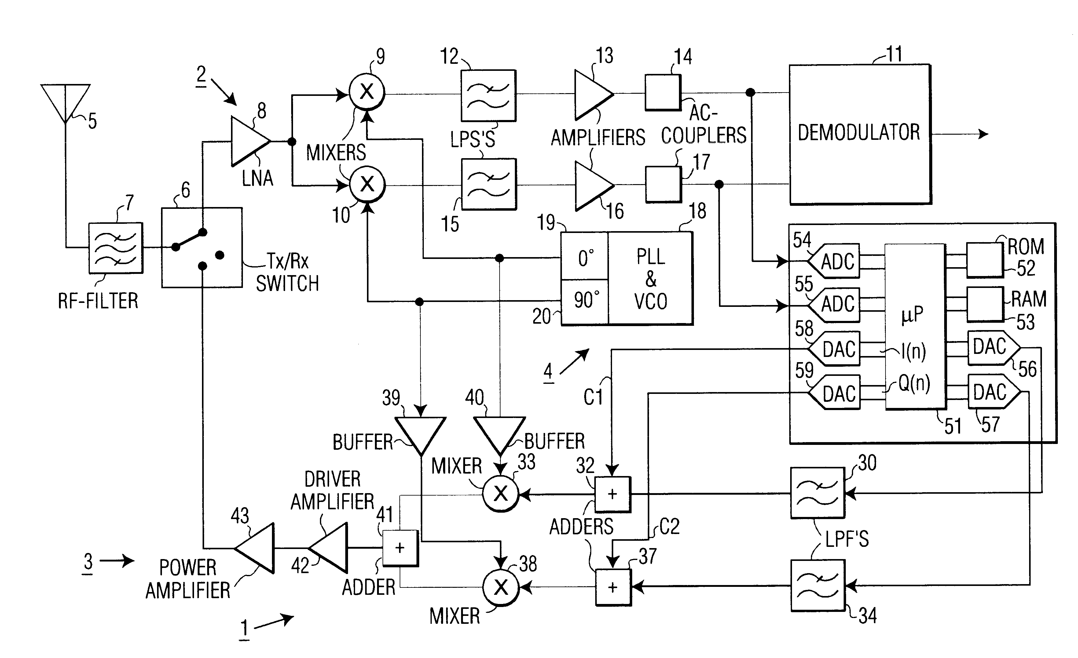
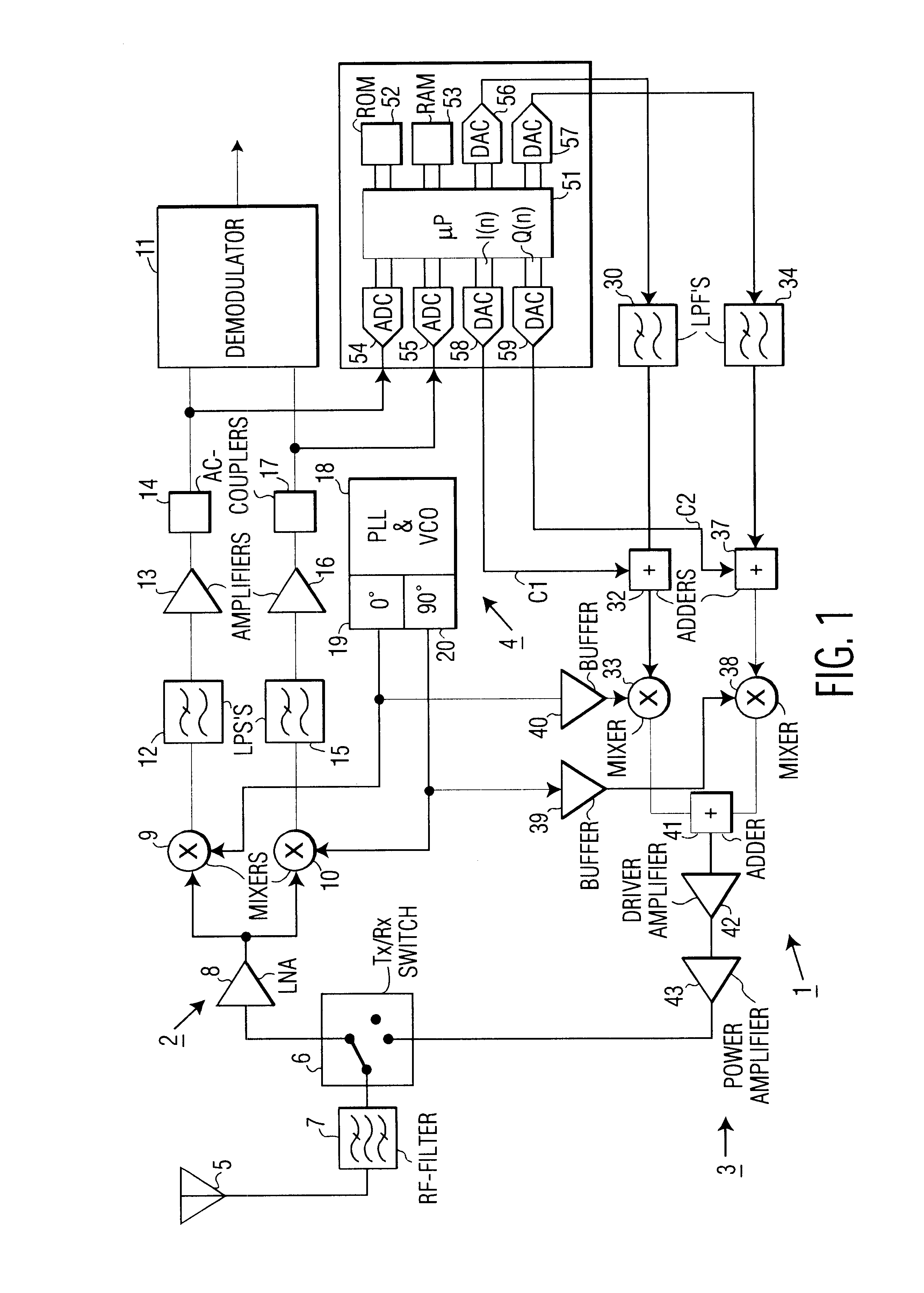
FIG. 1 is a block diagram of a transceiver 1 according to the present invention. The transceiver 1 comprises a receiver 2, a transmitter 3, and a local oscillator 4. The receiver 2 and the transmitter 3 are coupled to an antenna 5 via a transmit / receive switch 6 and an RF-filter 7. The receiver 2 comprises a low-noise amplifier (LNA) 8 that is coupled to a mixer 9 in an in-phase branch and to a mixer 10 in a quadrature branch. The mixer 9 is coupled to a demodulator 11 via a low pass filter (LPF) 12, an amplifier 13, and an AC-coupler 14. The mixer 10 is coupled to the demodulator 11 via a low-pass filter 15, an amplifier 16, and an AC-coupler 17. In accordance with the invention, the AC-couplers 14 and 17 comprise servo or feedback loops that perform DC-nulling of the receiver 2 and that provide a reference signal for calibrating the transmitter 3. As is well-known in the art, the common local oscillator 4 comprises a phase locked loop (PLL) and voltage controlled oscillator (VCO) ...

second embodiment

In the second embodiment, in the block 103, instead of putting a zero-input signal to the quadrature branches of the transmitter, a single tone quadrature signal is inputted, and sampling and determination of equality is done on the basis of averages of signal levels rather than on the basis of signal levels. This has the advantage that inaccuracies in the DACs 56 and 57, such as signal imbalances, are also compensated for.

When non-volatile memory is available for calibration data, calibration of the transmitter 3 may be done during manufaturing of the transceiver 3, possibly at a number of different temperatures. The manufacturer determined calibration values, at different temperatures may be stored in an a lookup table in non-volatile memory. In addition to the described calibration of the transmitter 3, a further calibration may be done when powering-on the transceiver 1, so as to compensate for big temperature changes. The transceiver 1 may then comprise a temperature sensor tha...


PUM


Abstract

A quadrature tranceiver has a transmitter, a receiver, and a common local oscillator. With the transmitter switched off and the receiver switched on, a DC-error in the receiver is nulled in servo loops in in-phase and a quadrature receiver paths. After settling, the servo loops provide output values that are freed of the DC-error. DC-nulling output values are then sampled and stored. After sampling, the servo loops are opened. Thereafter, the transmitter is switched on while inputting a fixed signal to the transmitter, and DC-signals injected into in-phase and quadrature paths of the transmitter are adjusted until the opened servo loops provide the same output signal as obtained at the end of the DC-nulling. Corresponding values of the injected DC-signals are then stored as transmitter calibration values.

Description

1. Field of the InventionThe present invention relates to a transceiver, more particularly to carrier leakage compensation in a transmit branch of a time division duplex transceiver that has a common local oscillator for the transmit branch and the receive branch of the transceiver. Such a transceiver can be a transceiver operating in the so-called 2.4 GHz ISM band, or any other suitable transceiver.2. Description of the Related ArtIn the U.S. Pat. No. 4,717,894 calibration of a vector modulator is disclosed using a scalar detector to measure the amplitude of an RF output signal of a transmitter. Calibration is done to compensate errors in vector modulated signals such as errors caused by carrier leakage, amplitude imbalance of the I and Q channels, and a quadrature phase error. Carrier leakage is the appearance of an output signal from the quadrature mixers even when the modulation inputs are grounded and can be caused by a non-zero offset voltage in a mixer, capacitive or inductiv...

Claims


Application Information

Patent Timeline
IPC IPC(8): H03C3/00H03D7/00H03C3/40H03D7/16H04B1/30H04L27/00H04B1/04H04B1/40
CPCH03C3/40H03D7/166H04B1/30H04B1/04
Inventor MOHINDRA, RISHI
Owner PHILIPS ELECTRONICS NORTH AMERICA CORP RK
Why Eureka
Try Eureka