Quench nozzle

a technology of quenching nozzle and quenching tube, which is applied in the direction of carburetizing air, lighting and heating apparatus, and separation processes

Inactive Publication Date: 2003-09-30
SHELL OIL CO
View PDF19 Cites 68 Cited by
  • Summary
  • Abstract
  • Description
  • Claims
  • Application Information

AI Technical Summary

Problems solved by technology

One of Assignee's designs, using a spray nozzle to introduce the quench oil for cooling the hot pyrolysis gas exiting the radiant section, did not work because of the difficulties in keeping the walls completely wetted.
This design created excessive thermal stress on the quench ring.
When this occurred, the quench oil flow wetting the quench tube wall was interrupted and this led to incomplete wetting of the quench tube wall.
Even without problems with the injection nozzles, the quench tube was subject to coke formation and plugging at the moving boundary between wetted and dry walls near the oil inlets.

Method used


Image

  • Quench nozzle
  • Quench nozzle
  • Quench nozzle

Examples


Embodiment Construction

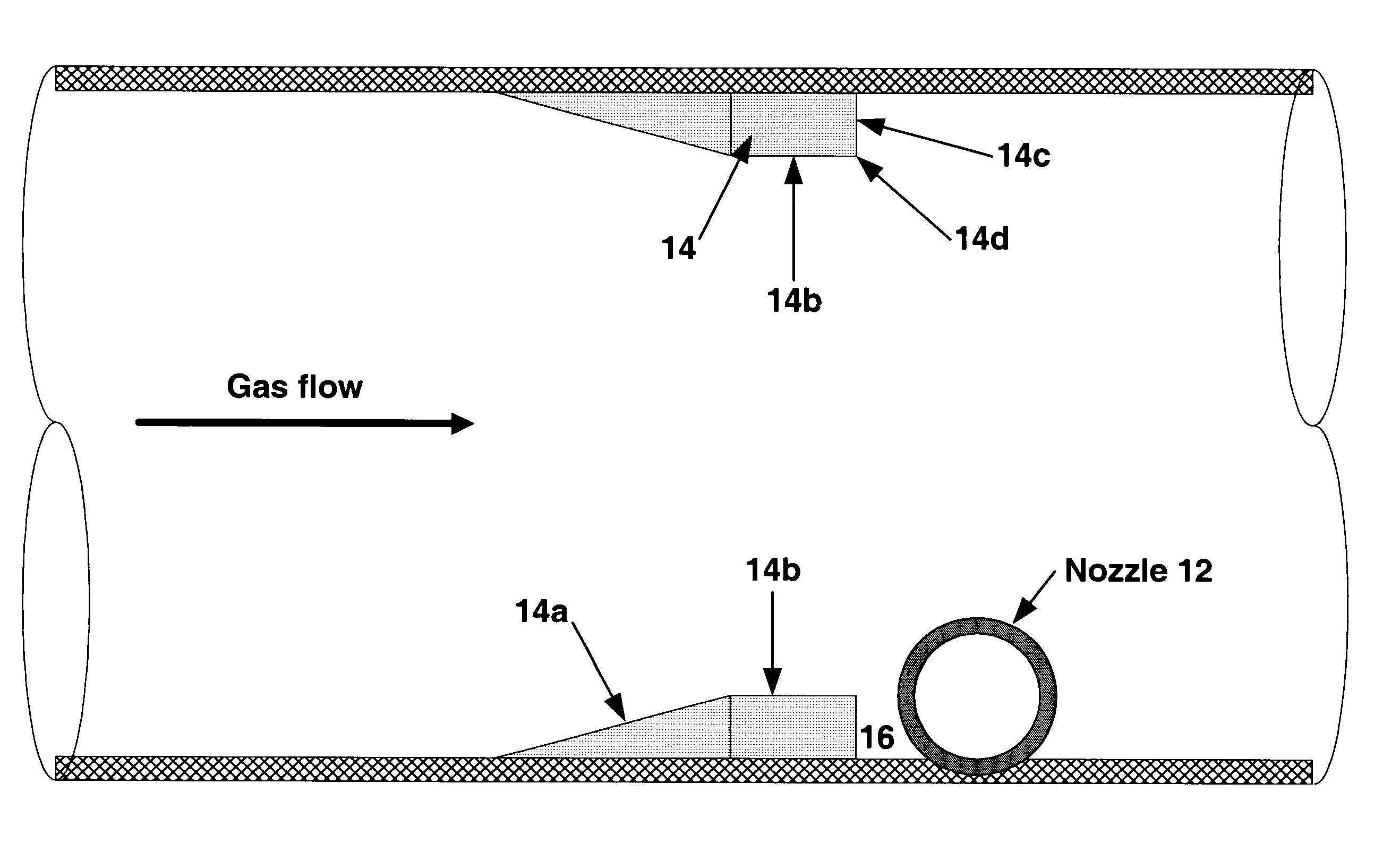
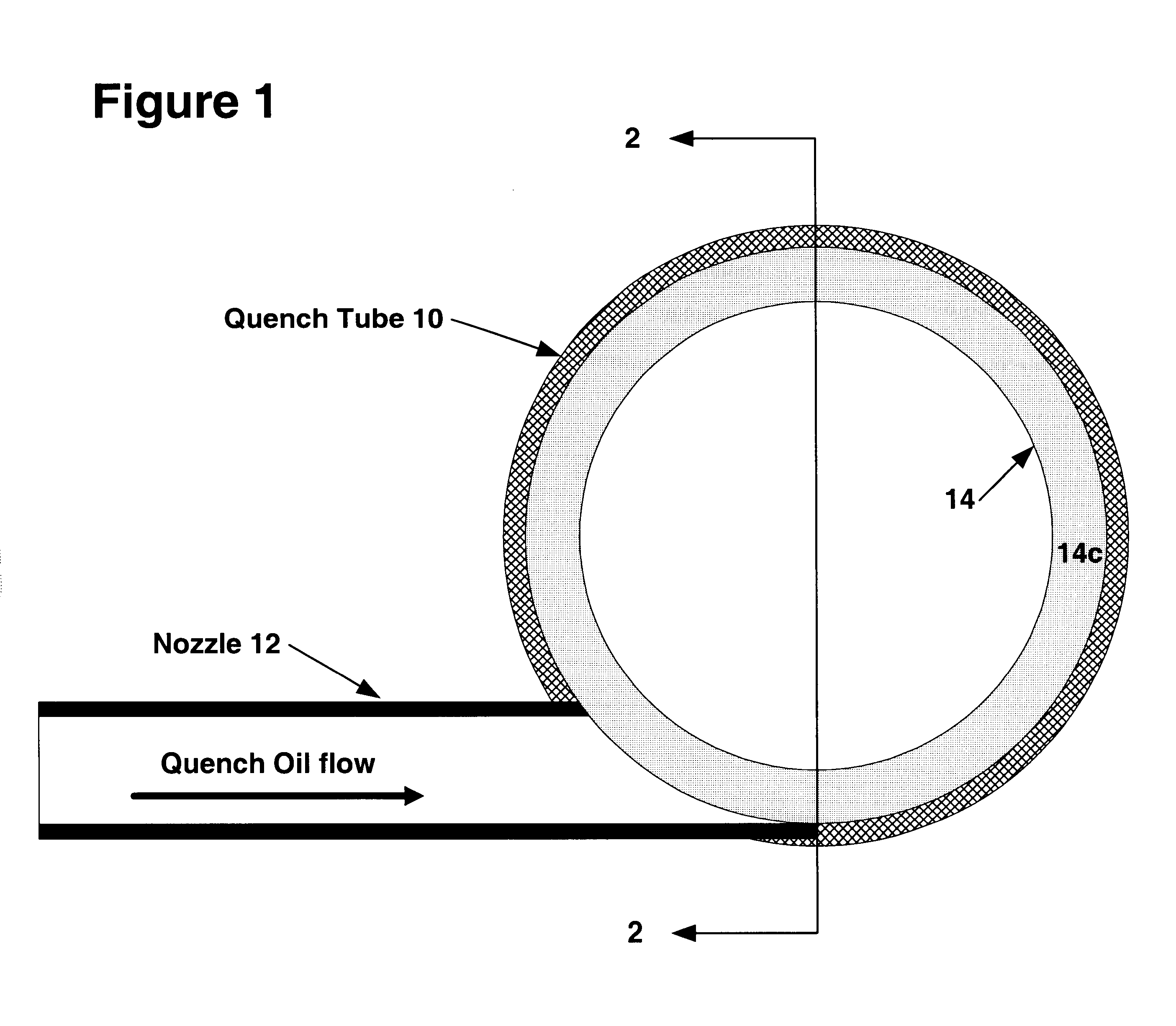
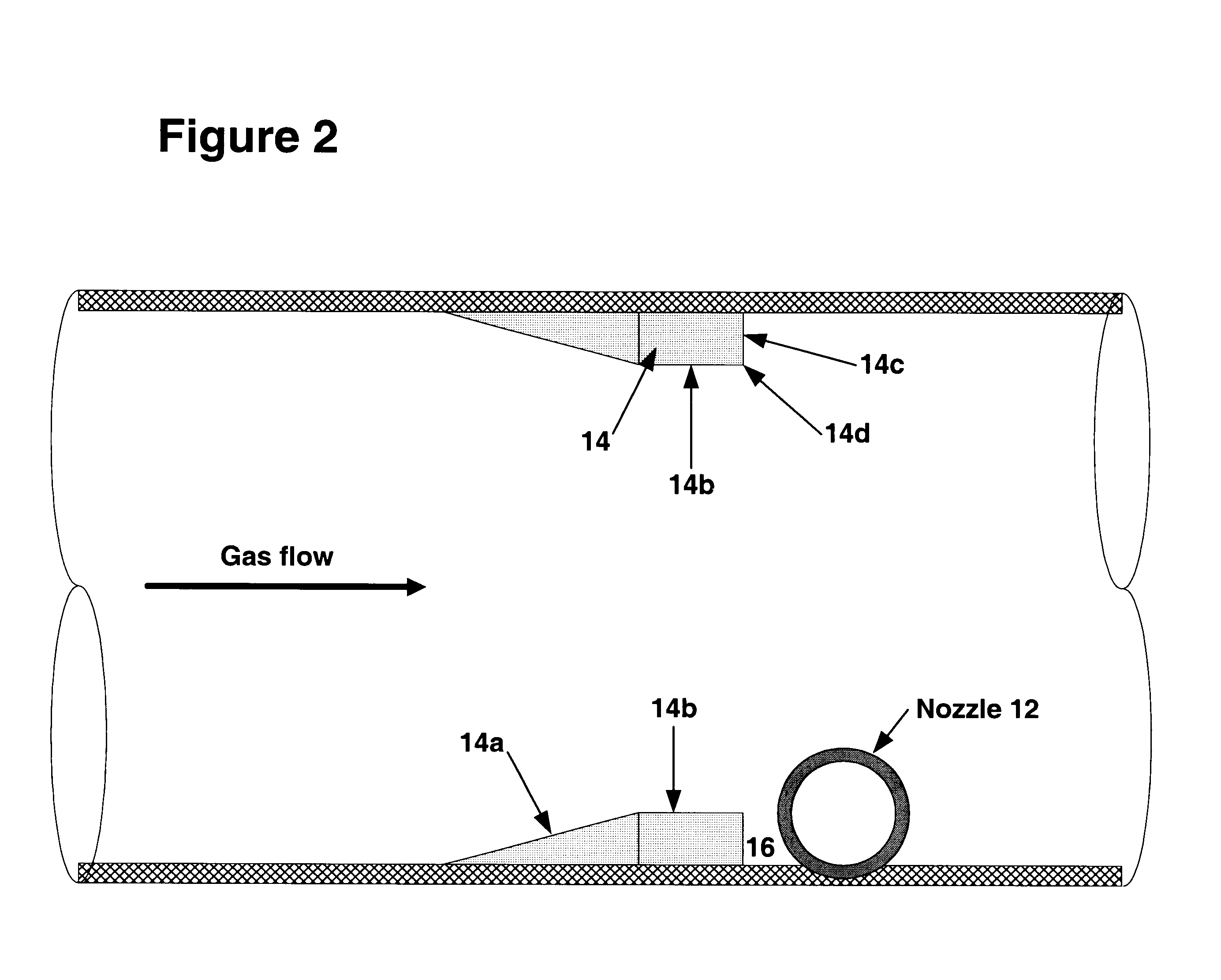
Furnaces in one of Assignee's plants utilizing the old quench nozzle design typically have to be shut down every fifteen days due to quench nozzle plugging in one or more of the ten quench passes in each furnace. In Assignee's test installation to prove the concept of the invention disclosed herein, the quench pass (with the old nozzle design) that was most prone to a plugging problem in the most frequently plugged furnace was selected for replacement. That nozzle was replaced by a quench tube 10 which utilized a Schedule 40 pipe having a nominal 8-inch diameter and was intersected by a nozzle 12 having a 11 / 2 inch I.D. bore. The quench liquid was injected at a flow rate of about 13 ft / sec (74 gal / min) into the hot gas stream flowing at about 200-250 ft / sec. The test quench pass nozzle system was operated for about one year with no downtime or plugging even though other nozzles (with the old design), including those adjacent to the test nozzle in the same test furnace, did plug due ...


PUM

PropertyMeasurementUnit
U2 /(Rg)aaaaaaaaaa
U2 /(Rg)aaaaaaaaaa
flow rateaaaaaaaaaa

Abstract

A quench nozzle design introduces quench oil tangentially into the quench tube which cools the hot gaseous pyrolysis products coming out of the hot radiant tubes in a pyrolysis furnace (in ethylene manufacture). Besides cooling the hot gases, the quench oil introduced into the quench tube by this nozzle design keeps the wall of the quench tube wetted, which is necessary to prevent coke deposition on the quench tube. The nozzle has one quench oil entry, which eliminates the need for any restriction orifice required to evenly distribute quench oil flows that would otherwise be required with several nozzle entries. Also, the one-nozzle oil introduction has a larger diameter than that required where more than one nozzle is employed in this service. The replacement of multiple nozzles with a single larger diameter nozzle eliminates plugging problems caused by coke solids or, coke solid precursors, present in the quench oil.

Description

1. Field of the InventionThe invention is generally directed to methods and apparatus for quenching a hot gaseous stream. The invention is more specifically directed to methods and apparatus for quenching the pyrolysis product from a pyrolysis furnace.2. Description of Related ArtAssignee's olefins plant was the first gas oil steam cracker plant in which it was recognized that wetting of the quench tube wall is essential in order to keep the quench tube from fouling because of coke deposits. One of Assignee's designs, using a spray nozzle to introduce the quench oil for cooling the hot pyrolysis gas exiting the radiant section, did not work because of the difficulties in keeping the walls completely wetted. Previous nozzle configurations included an external quench ring encircling the quench tube for distributing quench oil between three nozzles arranged 120 degrees apart around the quench tube. This design created excessive thermal stress on the quench ring. Later, it was modified ...

Claims


Application Information

Patent Timeline
Patent Type & Authority Patents(United States)
IPC IPC(8): C10G9/00F28F13/00F28F13/06F28C3/06B01J10/00C10G9/14
CPCC10G9/002F28F13/06Y10S261/54C10G9/00
Inventor NGAN, DANIEL YUK-KWANSTEIN, LOUIS EDWARDSANBORN, RICHARD ADDISONGARCIA, SR., RAUL JASSO
Owner SHELL OIL CO
Why Eureka
Try Eureka